An LED control system for model railroads
Introduction
After starting to fit some buildings of the layout with LED lights, I quickly realized that I would need dozens or even hundreds of light points. While it is possible to power them with a simple power supply and an on-off switch, I wanted to do more and be able to create effects such as flashing lights or be able to switch them on and off randomly or at a given time during the layout's virtual day and night.
In addition, wiring a high number of LEDs is an issue. Each individual LED requires its own resistor: not only for current control, to protect it, but also because most LEDs are far too bright and need to be significantly toned down. Having to fit each LED with its own resistor is not practical and figuring out the exact value of that resistor is not easy. Often, it’s only after installing the building on the layout, or even after taking photos, that the value of the resistors and the brightness of the light points can be adjusted.
A perfect LED control system would
- Not require complex wiring, even for hundreds of LEDs
- Not require resistors
- Allow the brightness of each LED to be controlled individually by software
Link to the Adafruit TLC59711 and TLC5947 page: https://learn.adafruit.com/tlc5947-tlc59711-pwm-led-driver-breakout/overview
Link to purchase these modules: https://www.adafruit.com/product/1455, https://www.adafruit.com/product/1429
Link to purchase these modules: https://www.adafruit.com/product/1455, https://www.adafruit.com/product/1429
Pulse Width Modulation
A single TLC59711 chip can control 12 LEDs with a 16-bit PWM output. The TLC5947 has even more channels: it can control 24 LEDs with a 12-bit PWM output.
PWM stands for Pulse Width Modulation, it is the proper way to control the brightness of an LED. Using PWM means that the control chip will switch each LED on and off very quickly (typically a few thousand times per second) and change their brightness by controlling the width of the pulses it sends to each LED, i.e. how many percent of the time the LED is on. At 50% brightness, the LED will be fully on 50% of the time and off 50% of the time. At 10% brightness, the LED will be on 10% of the time and so on. As this is happening much faster than the human eye can see, we have the impression that the brightness of the light changes.
A 16-bit PWM can control the brightness with 65536 steps. A 12-bit PWM has “only” 4096 steps, but this is more than enough for our application.
No more resistor
In addition, the TLC chips automatically limit the current flowing through the LEDs, this means that individual LED resistors are not required anymore! With the Adafruit boards, the maximum current is fixed and set to 15 mA per LED, which is safe for all standard LEDs.
Remote control
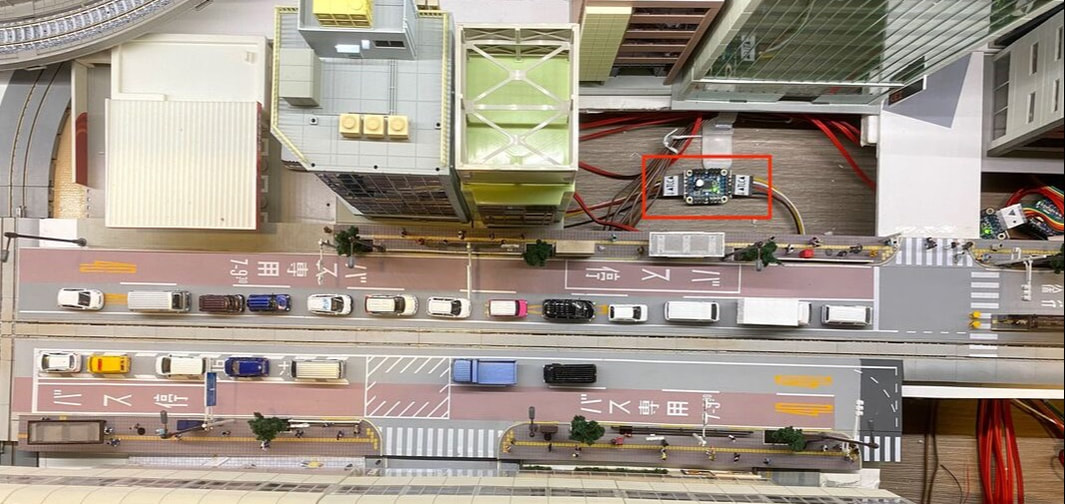
The TLC chips are remotely controlled by a microcontroller such as an Arduino or a Raspberry Pi. They can be daisy-chained, i.e. connected one after another to a single microcontroller in order to increase the total number of LEDs, or just control LEDs that are not close to each other. This architecture is very convenient for a model railroad; the microcontroller is installed in a corner of the layout, in an easily accessible place, while the TLC modules are scattered around the layout, connected to each other by just four (or five) wires.
Arduino or Raspberry Pi?
Adafruit provides setup guides for the Raspberry Pi and different types of Arduinos. Choosing between one or the other microcontroller will depend on your application, and pretty much any model of Arduino or Raspberry Pi will do the job. If you are starting from scratch, I recommend using an Arduino such as the Arduino Nano or Uno. The Raspberry Pi is only recommended if you want to attach it to a large display, or for running other applications at the same time.
Adafruit provides setup guides for the Raspberry Pi and different types of Arduinos. Choosing between one or the other microcontroller will depend on your application, and pretty much any model of Arduino or Raspberry Pi will do the job. If you are starting from scratch, I recommend using an Arduino such as the Arduino Nano or Uno. The Raspberry Pi is only recommended if you want to attach it to a large display, or for running other applications at the same time.
Pros |
Cons |
|
Arduino |
|
|
Raspberry Pi |
|
|
How to start?
Read the guide provided by Adafruit at the following page: https://learn.adafruit.com/tlc5947-tlc59711-pwm-led-driver-breakout/overview. They provide wiring diagrams and installation instructions for various microcontrollers. I have tested the Arduino Nano and the Raspberry Pi.
Sample code for Arduino
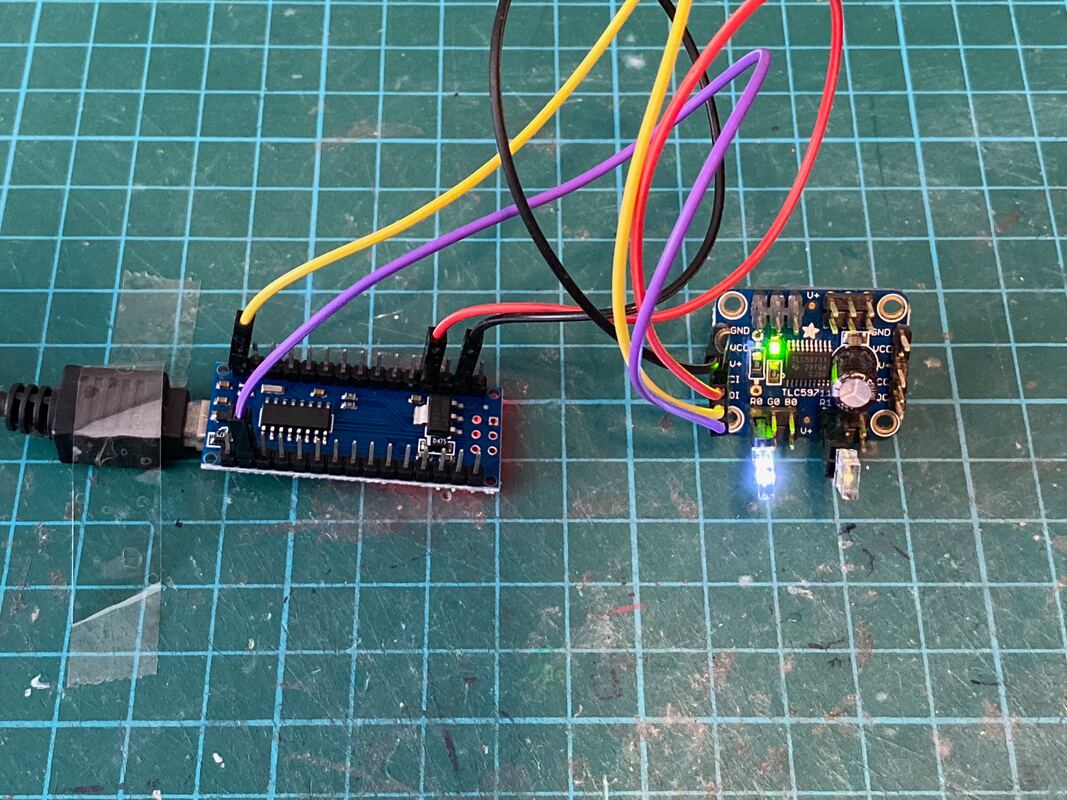
I have written a few sample programs to show how easy it is to use these modules. First, we will start with an Arduino programmed in C. My Arduino hardware setup for these samples is as follows:
- An Arduino Nano connected to a single 12-Channel TLC59711 module
- A white LED connected to the R0 / V+ output (output #0)
- A white LED connected to the R1 / V+ output (output #3)
The following program will flash the two LEDs (alternatively). In this program:
- After executing the setup() function, the code will indefinitely loop inside the loop() function
- The variable called “time” stores the value returned by the built-in “time()” function, the number of milliseconds that elapsed since the program was started.
- The following line uses the C “%” (called “modulo”) operator. This operator returns the remainder of the division of the two operands. In this case, the variable “time” will now contain a number incrementing every millisecond and going back to zero when it reaches one thousand.
- Depending of the value of “time”, the following lines will set the two LEDs, #0 and #3, on or off. The two LEDs will thus alternatively flash with a period of one second (i.e. one thousand milliseconds).
- “tlc.write()” is called to send the commands the LED modules. It is followed by a call of “delay(50)” which will pause the execution of the code for 50 milliseconds. It is important to note that the code in the loop executes once every 50 milliseconds and never stops. The status of the LEDs is refreshed 20 times per second. You can change the value of the parameter of the delay function to decrease or increase the frequency.
How to flash two LEDs (or more) at different frequencies? In the following program, we call the % operator two times, with different operands:
- “if (time % 800 > 400)” will return false for the first 400 milliseconds of every 800-millisecond period, and true the rest of the time. The first LED will flash with a period of 0.8 seconds.
- “if (time % 300 > 150)” will return false for the first 150 milliseconds of every 300-millisecond period, and true the rest of the time. The second LED will flash with a period of 0.3 seconds.
Sample code for Raspberry Pi
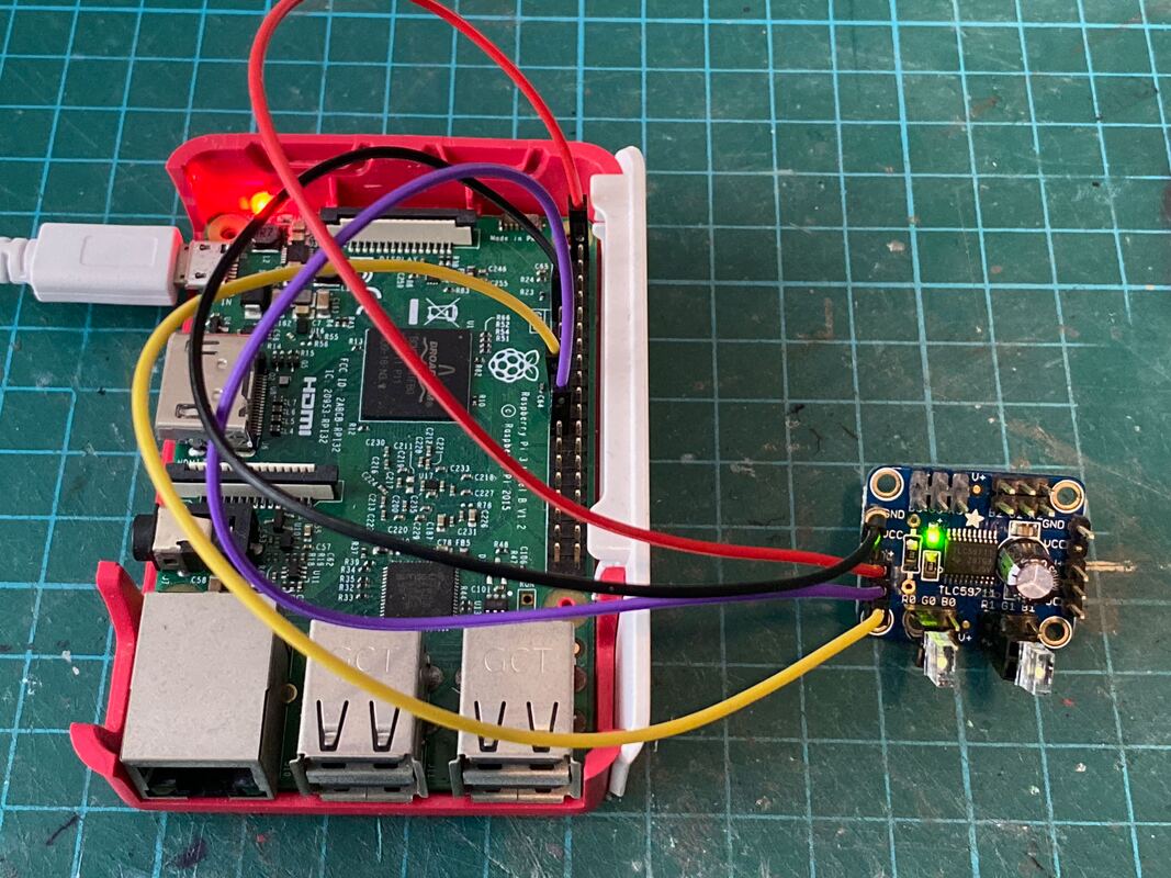
The following sample programs are written in Python for a Raspberry Pi (any model will do). The hardware setup for these samples is as follows:
The following sample programs are written in Python for a Raspberry Pi (any model will do). The hardware setup for these samples is as follows:
- A Raspberry Pi connected to a single 12-Channel TLC59711 module
- A white LED connected to the R0 / V+ output (output #0)
- A white LED connected to the R1 / V+ output (output #3)
The following program flashes the first LED with a period of 0.8 seconds:
- The time.perf_counter() function returns the time ins seconds (it’s a floating point number).
- With the line “if now % 0.8 > 0.4:”, we use the same remainder operator is described above, and we test if the remainder of the time is higher than 400 milliseconds. If so, we switch the LED on (at a brightness of 1000).
The following program uses exactly the same functions to flash to LEDs at different frequencies.
Finally, the program below shows that the Raspberry Pi is capable of more complex mathematical functions. It flashes two LEDs alternatively, but using gradual brightness and even Gamma Correction.
After calling the time.perf_counter() function, we compute two variables brightness_r0 and brightness_r1 that will gradually increase and decrease between 0 and 1. The line “brightness_r0 = int(1000.00 * (brightness_r0 ** 1.8))” transforms the variable brightness_r0 to apply Gamma Correction. As explained here (https://learn.adafruit.com/led-tricks-gamma-correction/the-issue), applying Gamma Correction improves the eye perception of the different levels of brightness of LEDs, making changes look more gradual and realistic.
After calling the time.perf_counter() function, we compute two variables brightness_r0 and brightness_r1 that will gradually increase and decrease between 0 and 1. The line “brightness_r0 = int(1000.00 * (brightness_r0 ** 1.8))” transforms the variable brightness_r0 to apply Gamma Correction. As explained here (https://learn.adafruit.com/led-tricks-gamma-correction/the-issue), applying Gamma Correction improves the eye perception of the different levels of brightness of LEDs, making changes look more gradual and realistic.


