|
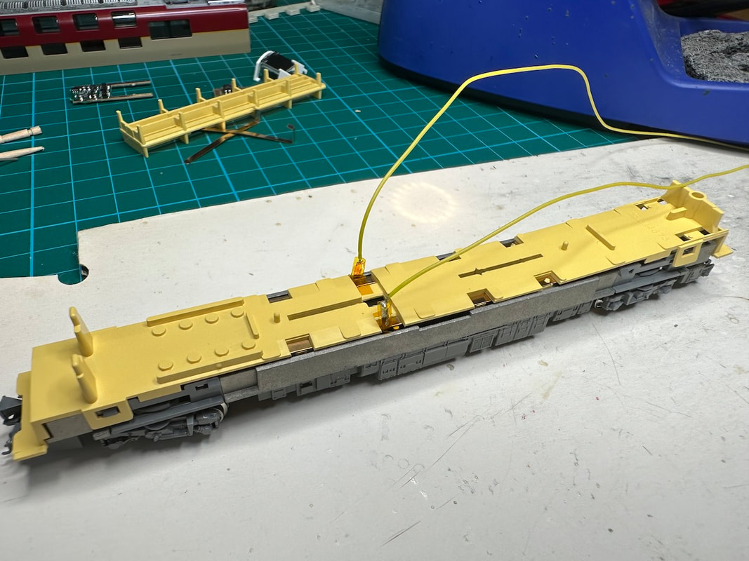
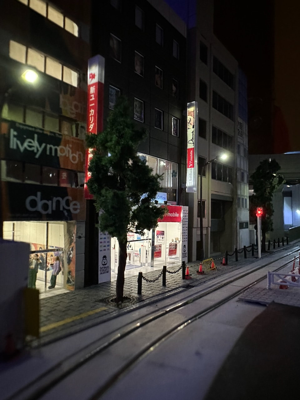
On the layout, I use an LED control system described here: https://shin-yukari.weebly.com/led-controller.html. It is based on Adafruit 12-Channel 16-bit PWM LED Driver modules spread all over the layout. They allow a central computer (a Raspberry Pi in my case) to control the hundreds of LEDs fitting the various buildings. In addition, I needed a similar control box on my workbench. This is a description of the system I have designed. 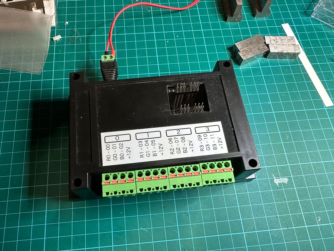 It uses the same Adafruit module and exposes the 12 LED outputs on terminal blocks with push-in connection, suitable for temporary connection (no soldering required, no screw). 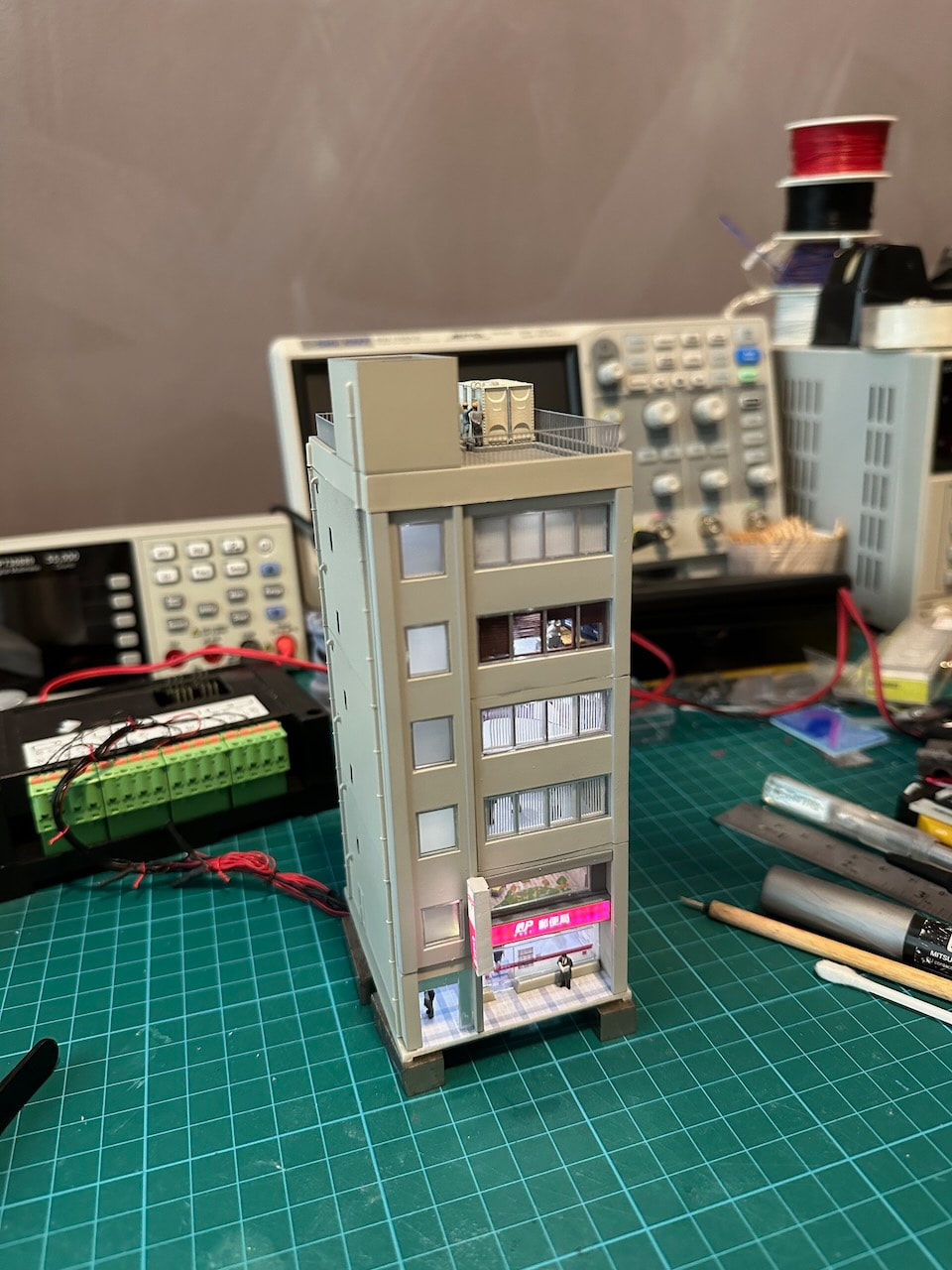 Here we see a building "under construction", with its wires attached to the control box. 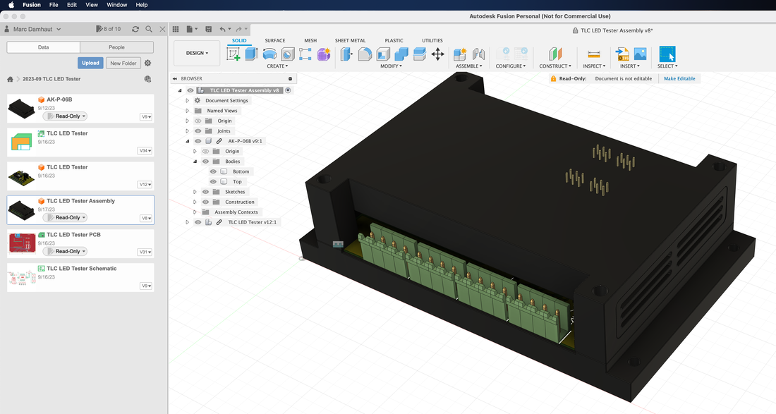 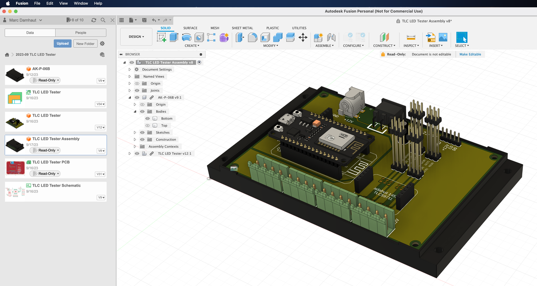 I have designed the PCB in Autodesk Fusion 360. The system is based on an ESP32 microcontroller connected to the Adafruit module and to the various connectors and terminal blocks. The ESP32 exposes a web page used to individually set the brightness of each LED. 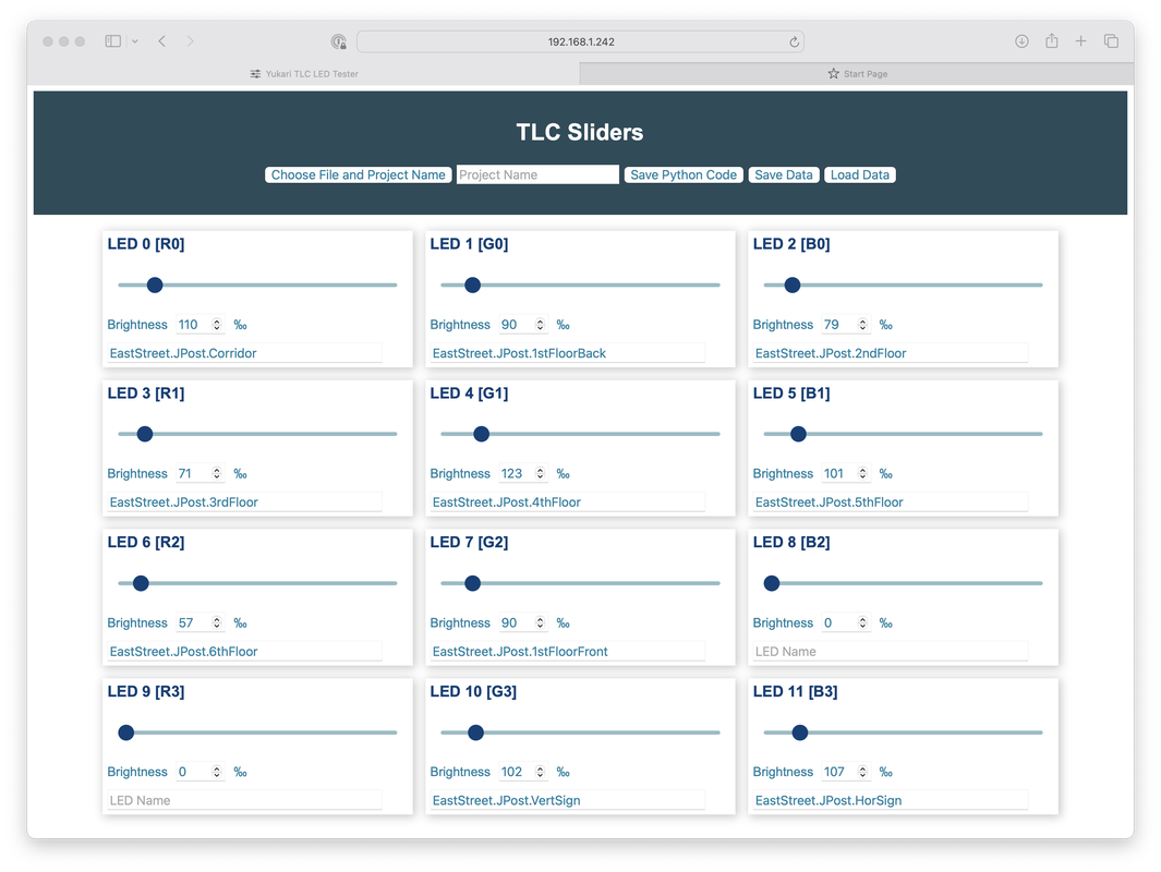
0 Comments
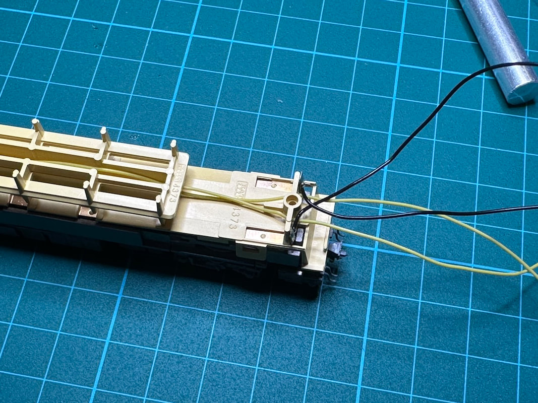
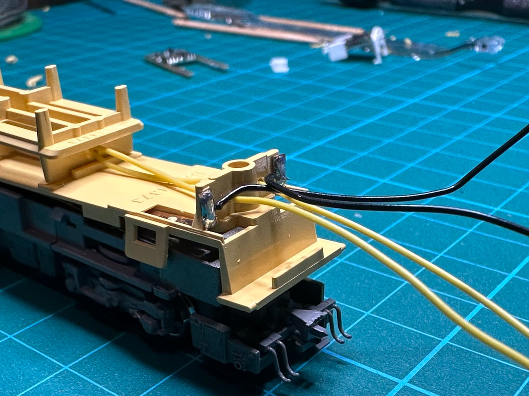
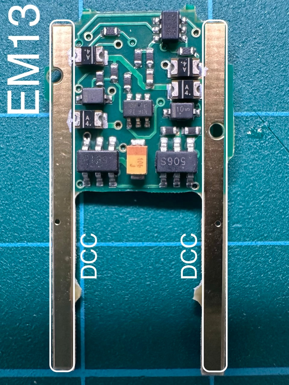
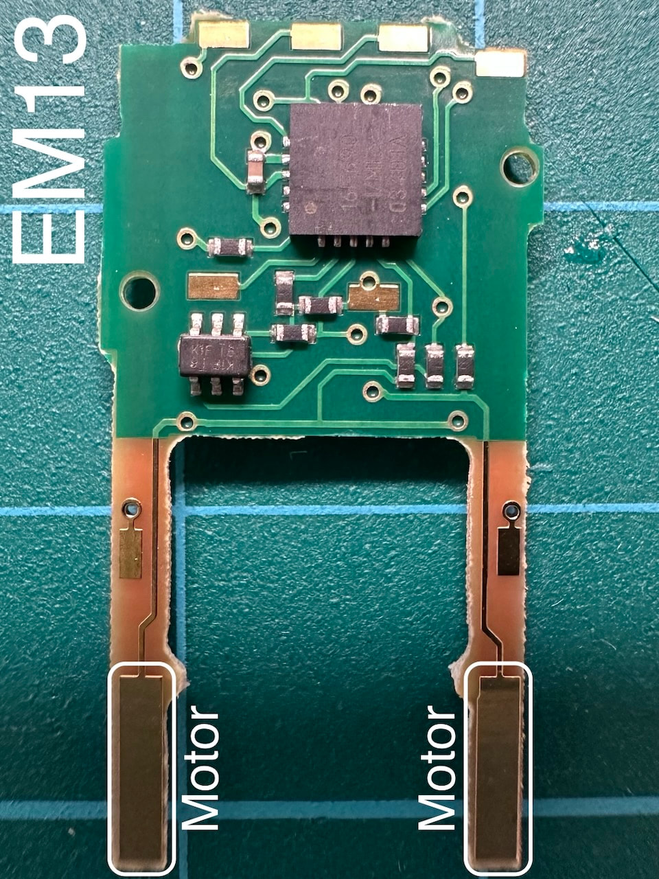
I have finally purchased a 3D printer. I chose the Elegoo Mars 4 Ultra 9k, along with their Mercury XS Bundle, including the washing and curing stations. The Elegoo Mars 4 Ultra is a small printer, the maximum build volume is only 153.36 x 77.76 x 165mm, but the resolution is super high: 18μm (that's 0.018mm). This is suitable for me as I will only print small models, but I need them super detailed. The photos below show the complete setup, and the very first print! The roof is fitted with accessories that have been 3D-printed. I built simple light boxes to simplify the lighting of the building. These are the steps I have followed to install EM13, FR11 and FR12 decoders in the Kato 10-1564 "Sunrise Express". This is a custom install that requires modification of the light boards and soldering of (very small) wires directly to the decoders. No modification of the car's frame was required. Part 1. EM13 motor decoder
Part 2. FR11 interior light decoder
I've used etched 1:150 cute animal barriers that can be purchased here https://neonnoirdesigns.booth.pm/items/5377423 https://www.etsy.com/listing/1277143858/1150-scale-etched-animal-barriers Many designs are available. Look for the Neon Noir Designs shop on Booth.pm or Etsy. Painting:
The front signboard backlight is made of a piece of polyester scored at precisely spaced intervals to spread the light evenly. 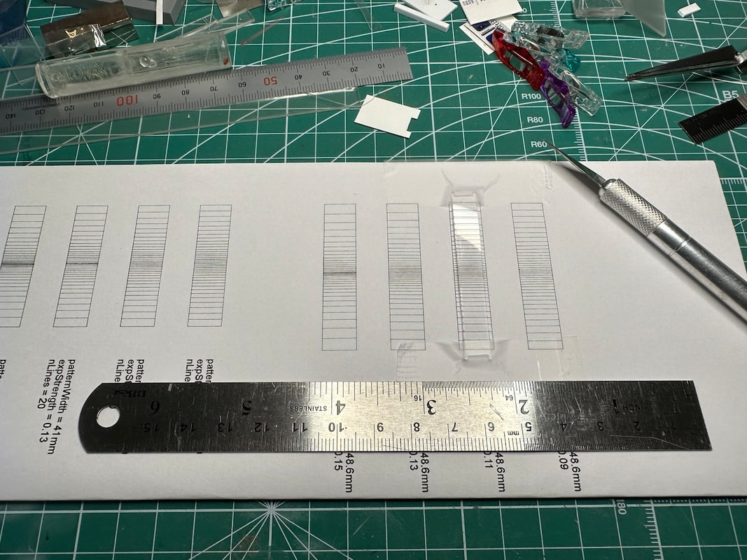 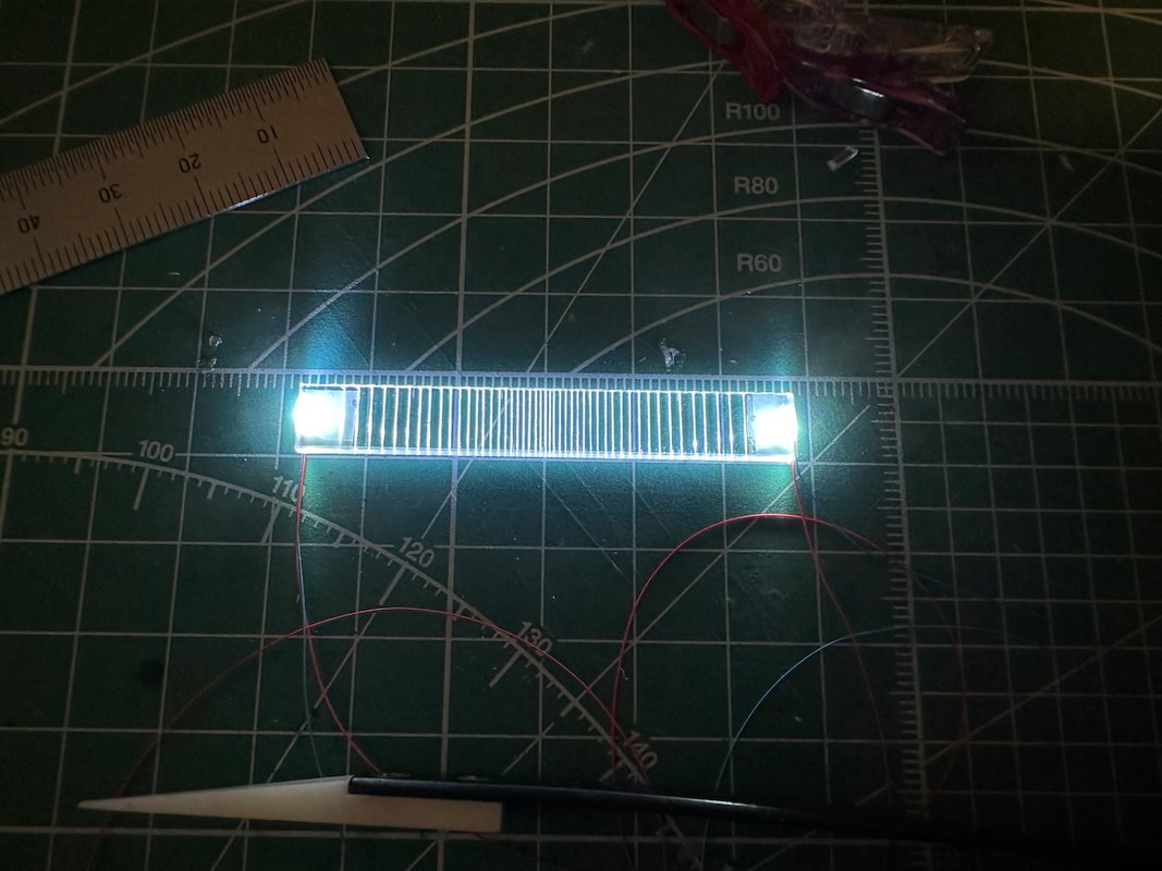 After googling a bit, I learned that the intensity of the light in the backlight panel decreases exponentially. I then created a small python script that generates lines spaced exponentially, and used the resulting document to score the transparent polyester (or acrylic) sheet. The result is a uniform light distribution, even if there are only two LEDs at both ends of the signboard. Next to the school dance building is the Softbank building. It is based on the very popular Tomix 4051 Square building set (brown). https://www.tomytec.co.jp/tomix/products/n/4051.html Complete with 3D-printed figurines... ... and a nice wooden bench. The top floor is the music studio, with a nice glass roof. Each storey is lighted individually, using small light boxes. The decals have been designed in my preferred vector graphics application, Affinity Designer. 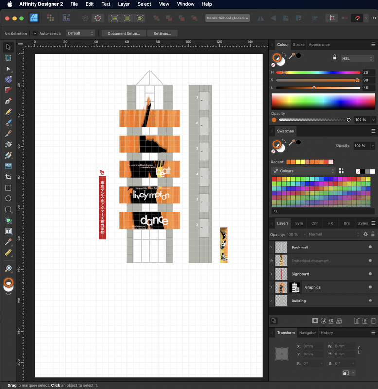
The building next to the construction site will be a Dance School, inspired by the Tokyo Dance Haiyu & Butaigeijutsusenmon School building in Shibuya.
I needed to add more signals, so I made a new version of my Arduino Nano-based DCC signal controller. This one can control up to ten Tomix signals. Working on the construction site this week. First, new signboards and decals 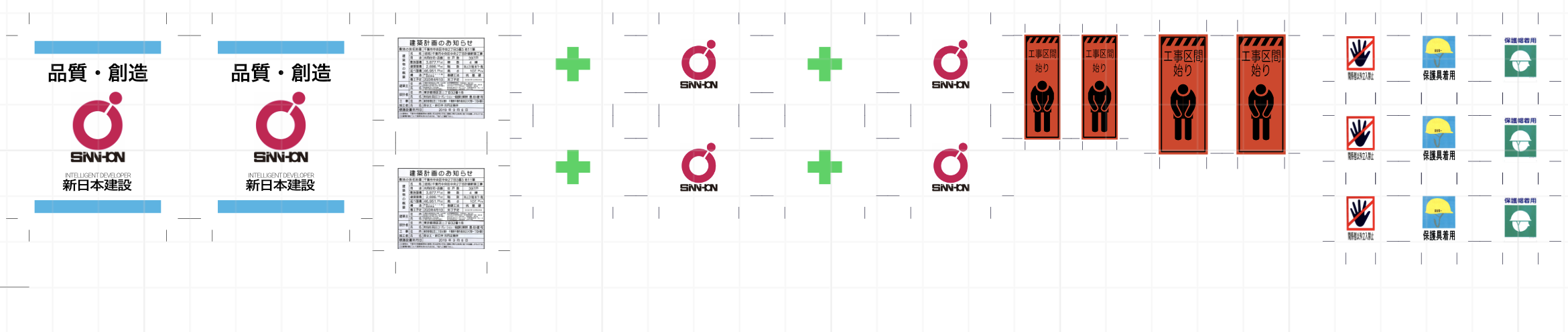 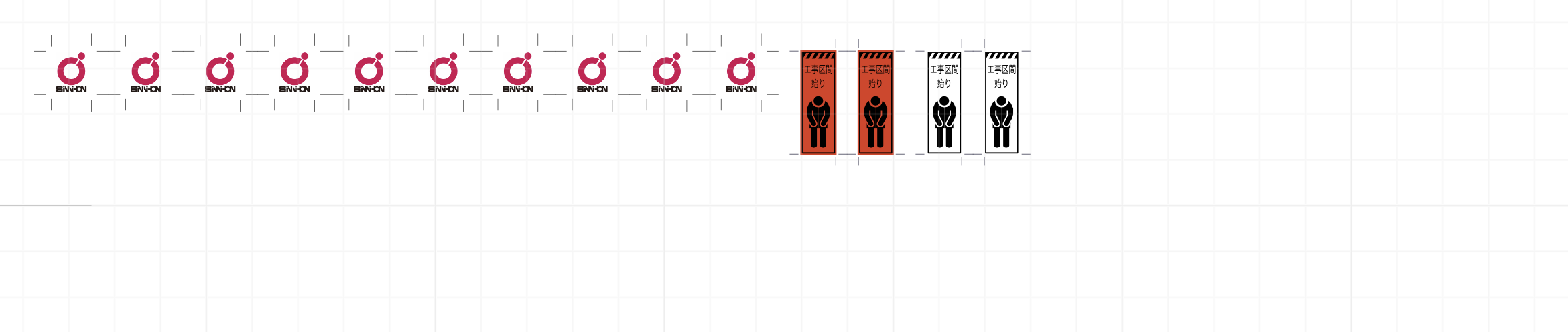 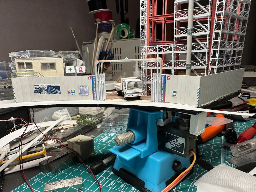 Then, the first tests of the moving crane. The servo motor (controlled by an Arduino Nano) is right below the board. The rotation is not super smooth, I'll have to work on that! I am continuing the work on the construction zone (next to the tower crane). This area is stuck between the train and the tram tracks, so it has a strange curved shape. I have prepared more photo-etched parts this summer, for the scaffolding and the fence. The building frame is made of Evergreen styrene strips and beams. |
Categories
All
Latest videoArchives
November 2023
|

 RSS Feed
