|
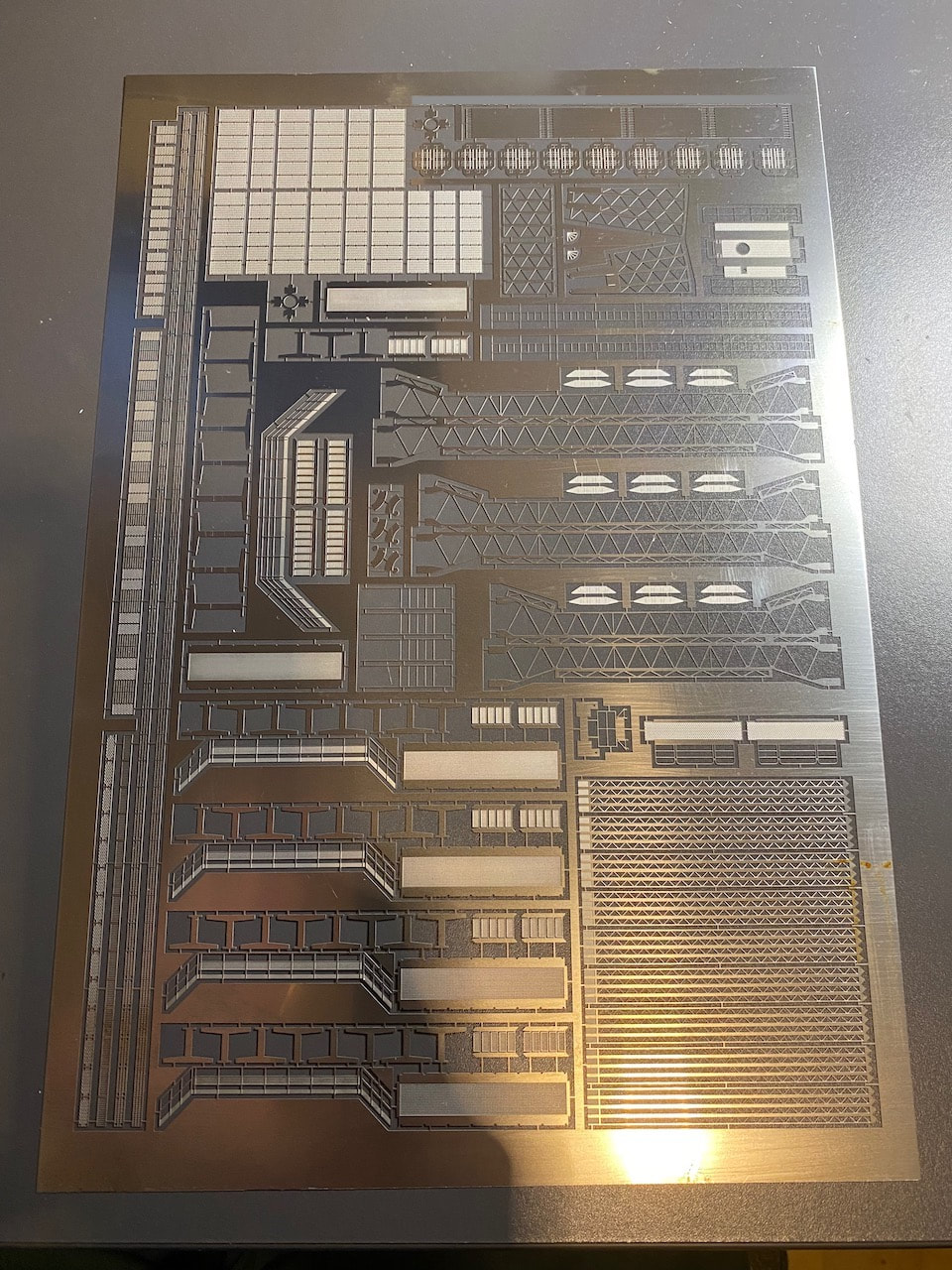
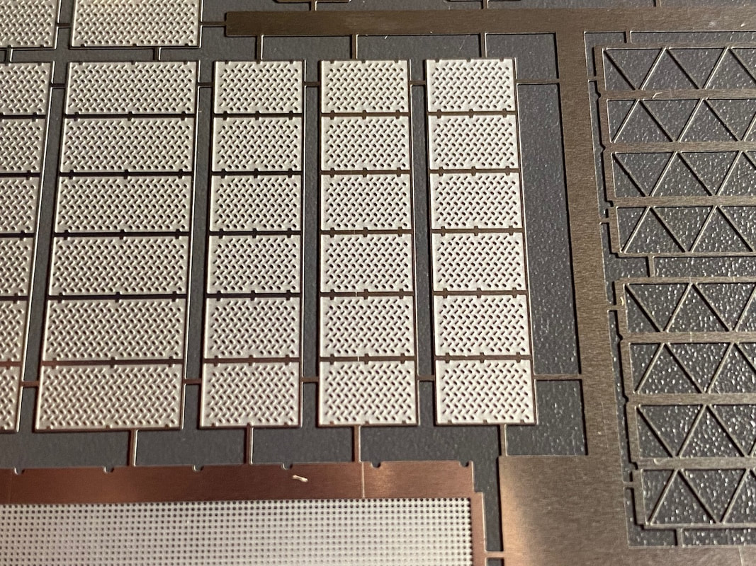
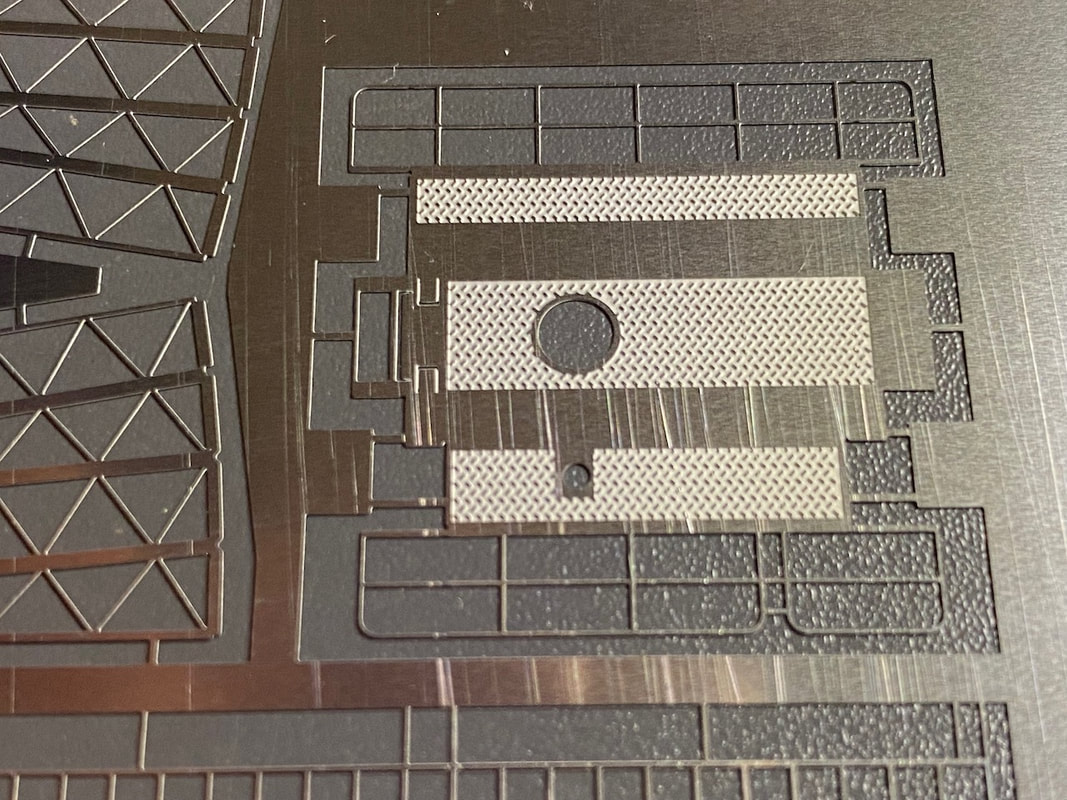
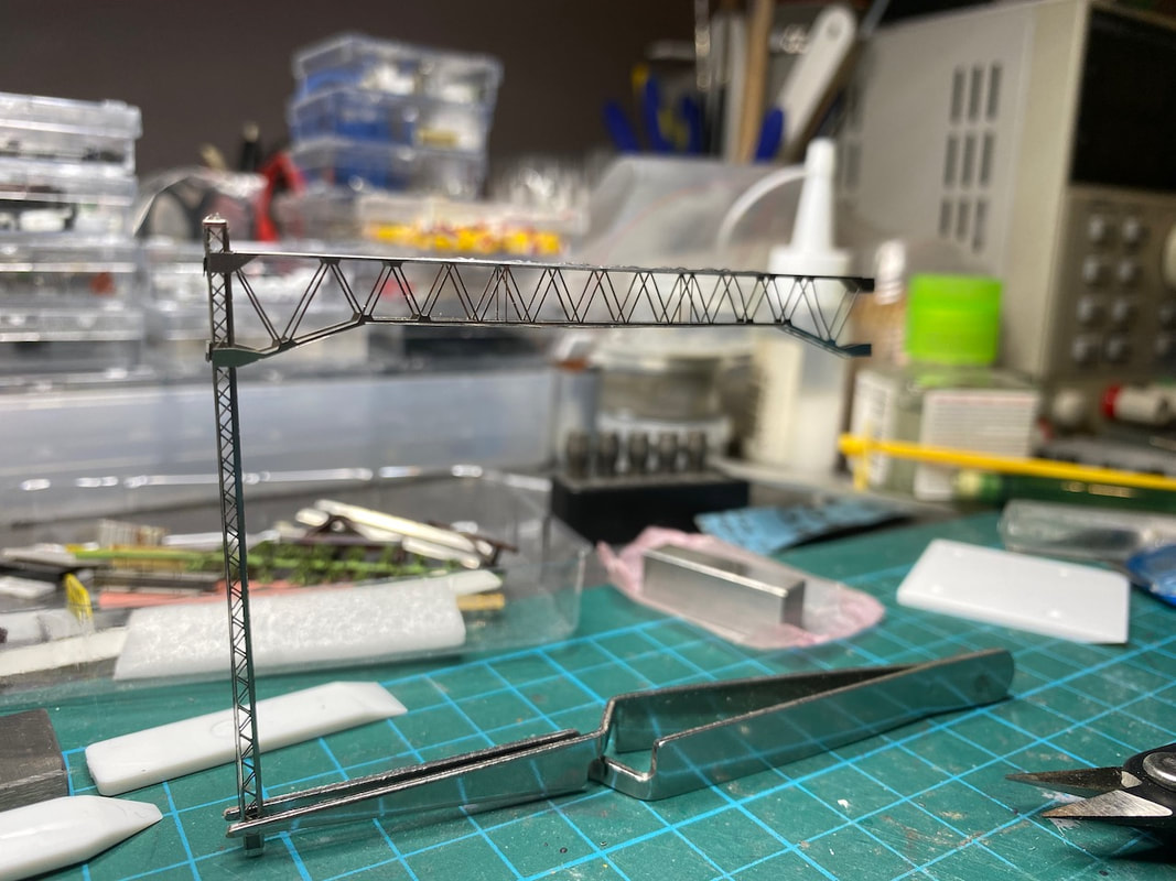
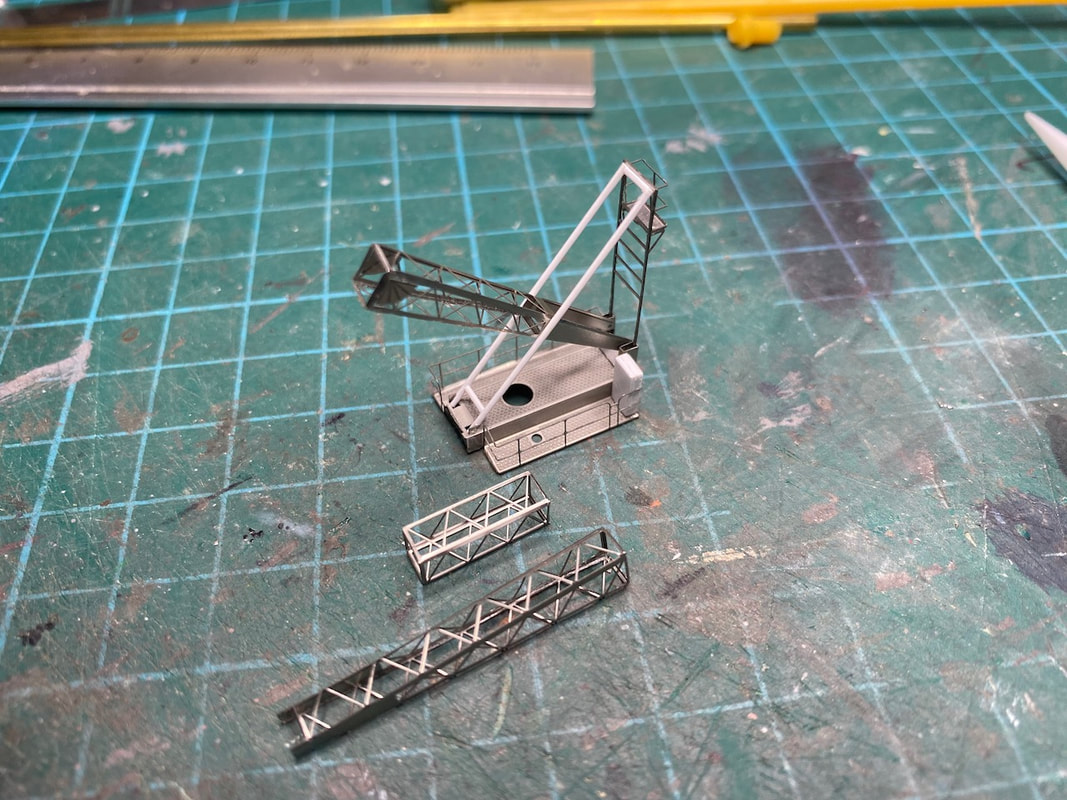
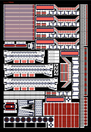
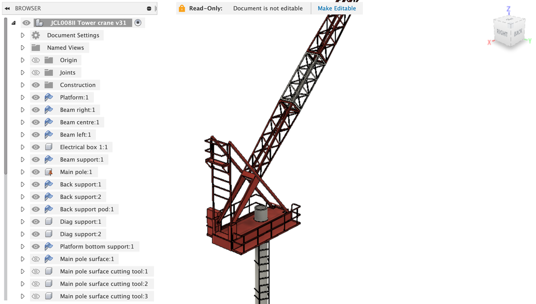
Part of the first photo-etching project, I built a tower crane, which will be the focus point of the new construction area. The tower crane is largely inspired by a real crane, the JCL008II. This is the photo-etched stainless steel sheet as it came back from manufacturing. The details are perfect, very precise. The workflow is as follows:
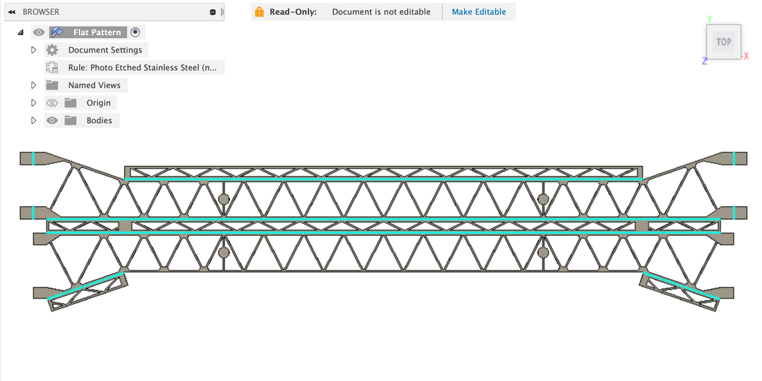
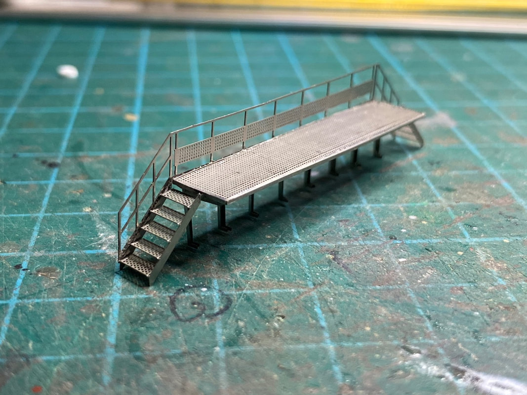
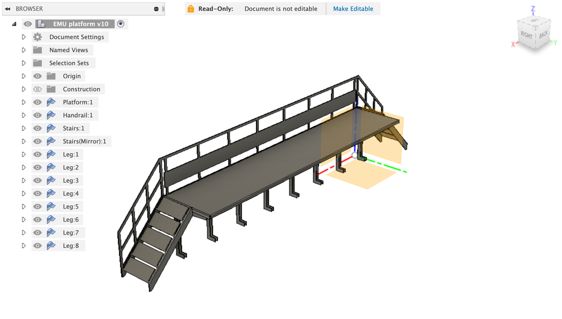
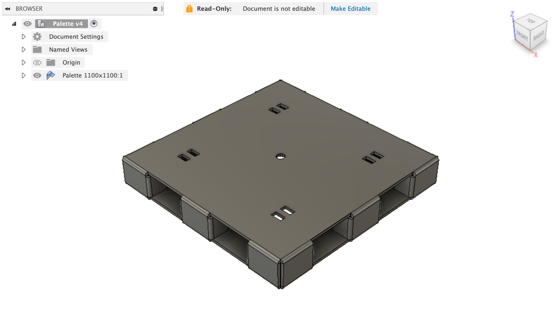
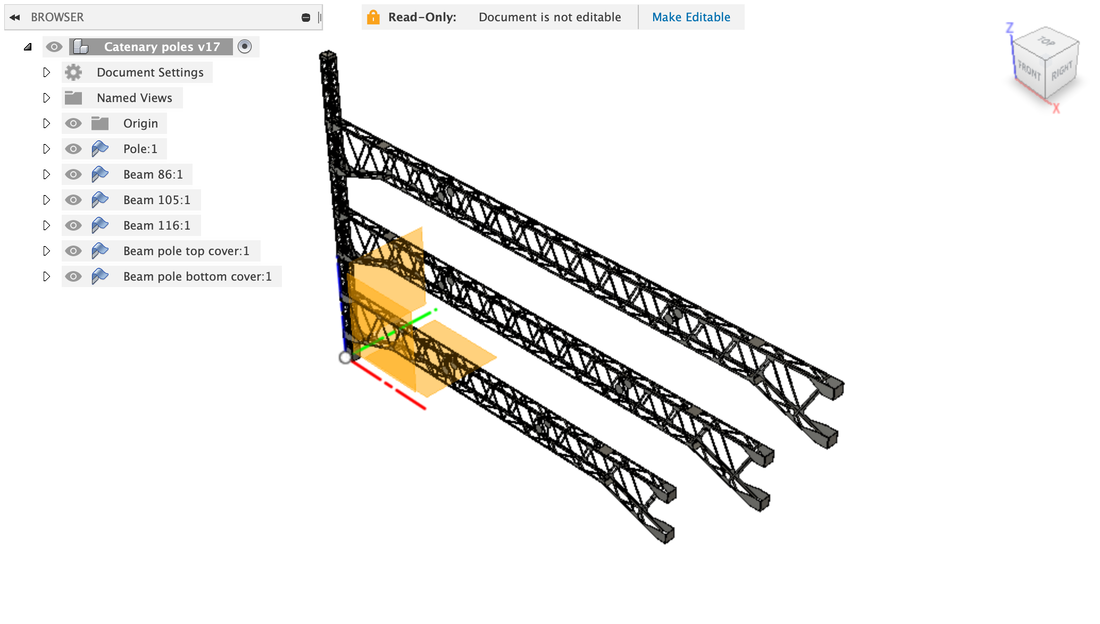
I am experimenting with photo-etching to make highly-detailed parts such as catenary poles or steel platforms. The parts are first modelled in 3D in Autodesk Fusion 360 using the Sheet Metal module. Fusion 360 is a powerful CAD/CAM/PCB professional tool available free of charge for personal use (check https://www.autodesk.com/products/fusion-360/personal). These are a few examples of objects designed using this software.
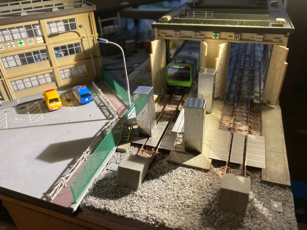
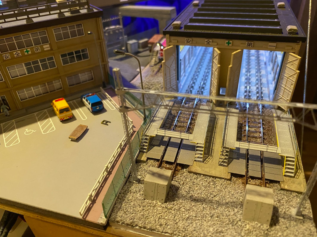
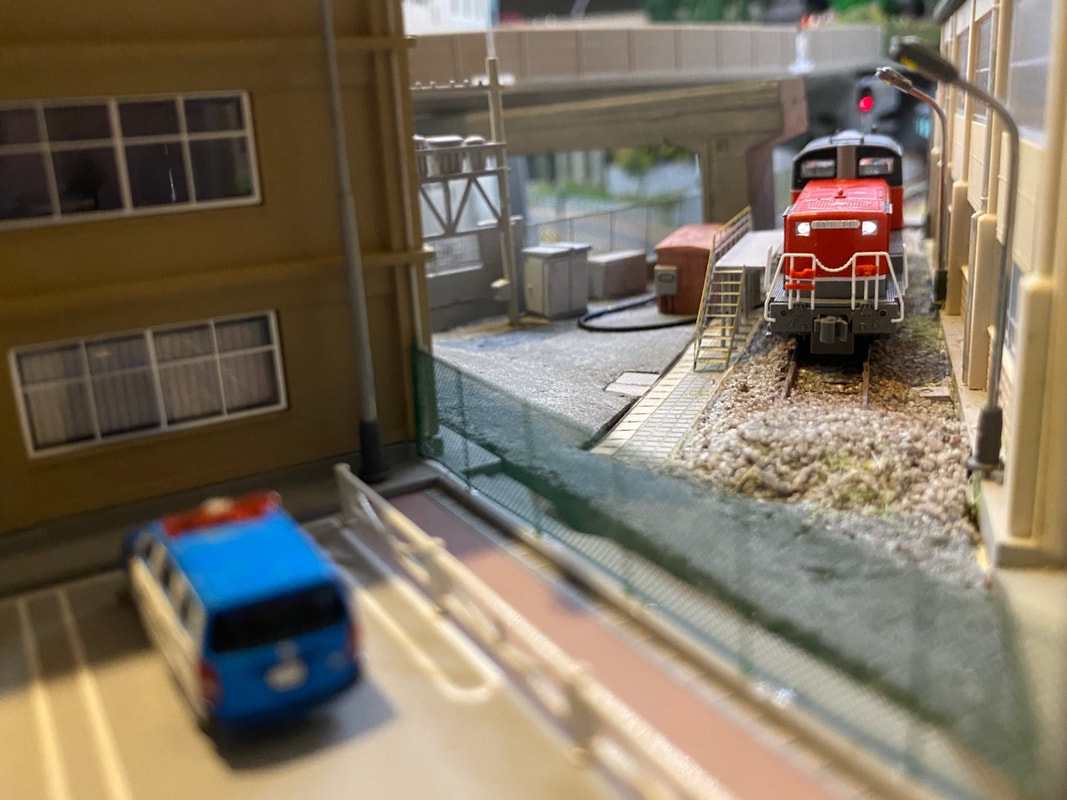
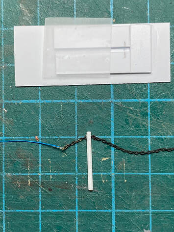
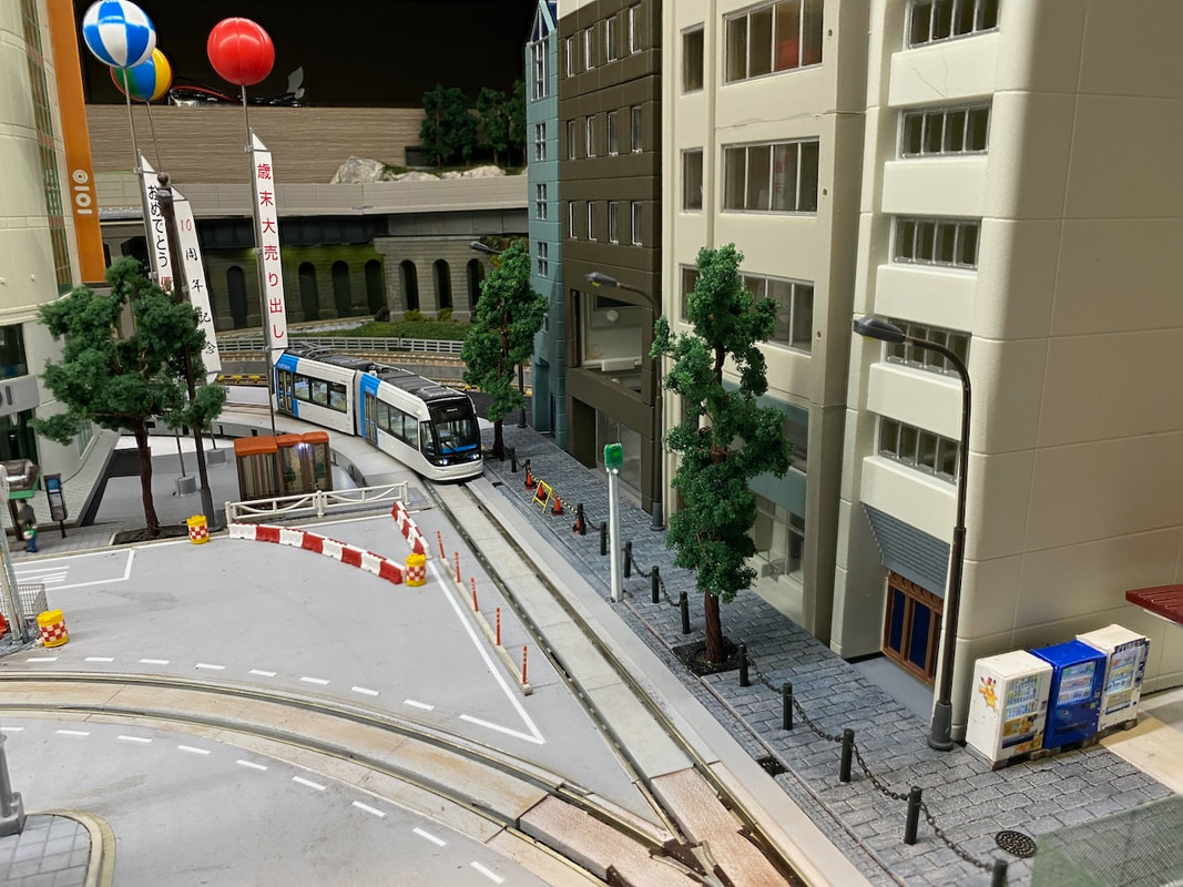
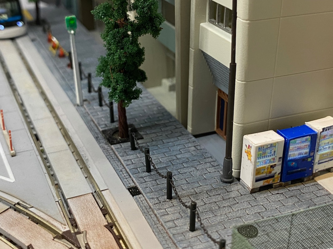
The pavement is made with TGW (Tsugawa) NDP-1 New Plastic Design Paper - Brick 50, airbrushed with Tamiya XF2 Flat White 96% + XF1 Flat Black 4%, then unevenly dry brushed with Tamiya XF66 Light Grey (which appears very blue), then weathered with AK-Interactive Neutral Grey Wash AK677 diluted in AK049 Odorless Thinner. That's not exactly what I was going for (I have tried many things, still learning here...). It looks darker and "older" than what I wanted, but I like the large tiles. Let's say it's a pedestrian shopping street that has been recently renovated using large "fancy" stones. 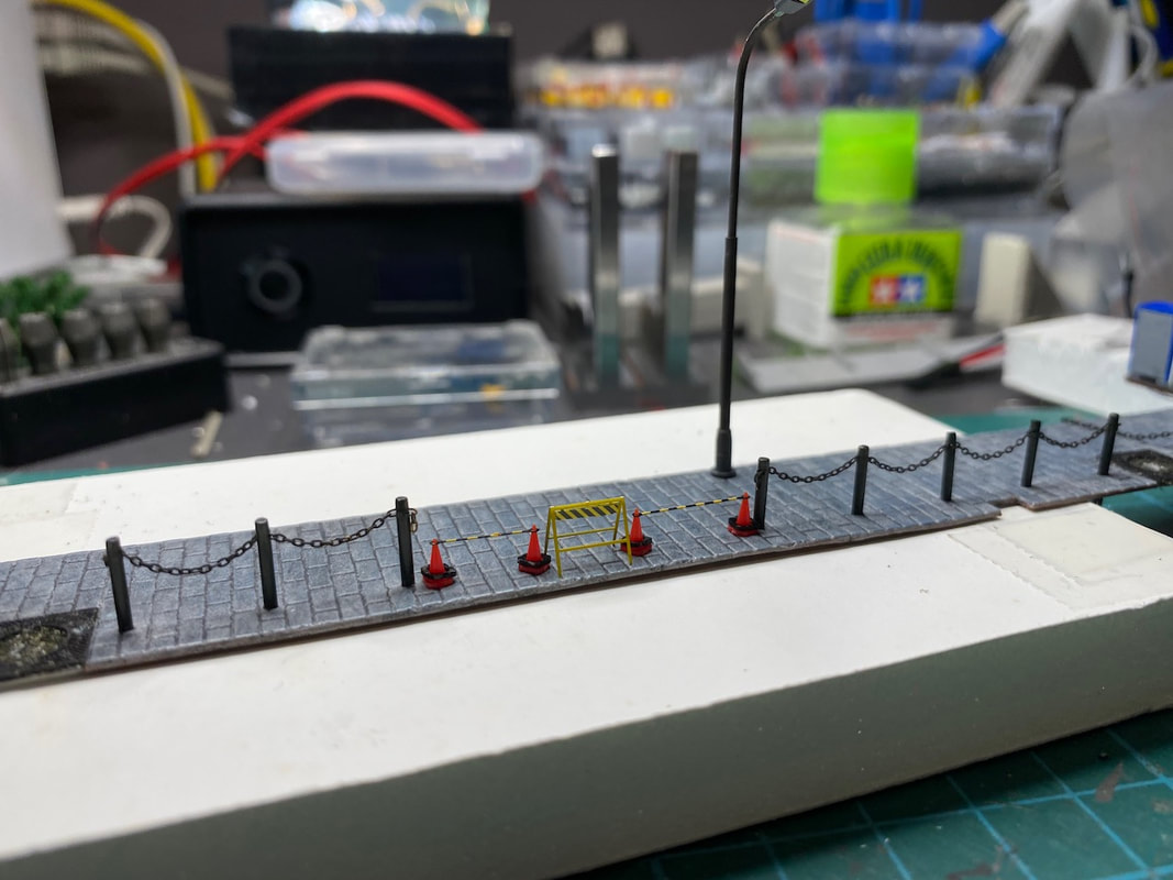 The custom made decals are quite large and require a lot of patience! I have purchased and just received this CY700001 2set 1/700 Scale Model Ship 0.55mm Black Anchor Chain. https://www.aliexpress.com/item/1005002942018738.html 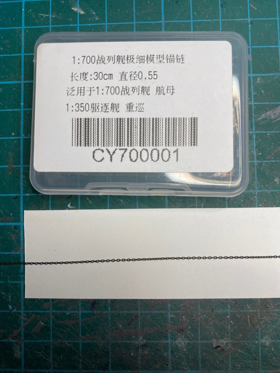 It's meant for a model ship but I think I can use it to build a fence similar to this https://www.sunpole.co.jp/supply/post-8159/ The chain link diameter is 0.55mm = prototype 82mm. Maybe a bit large, but should be ok. 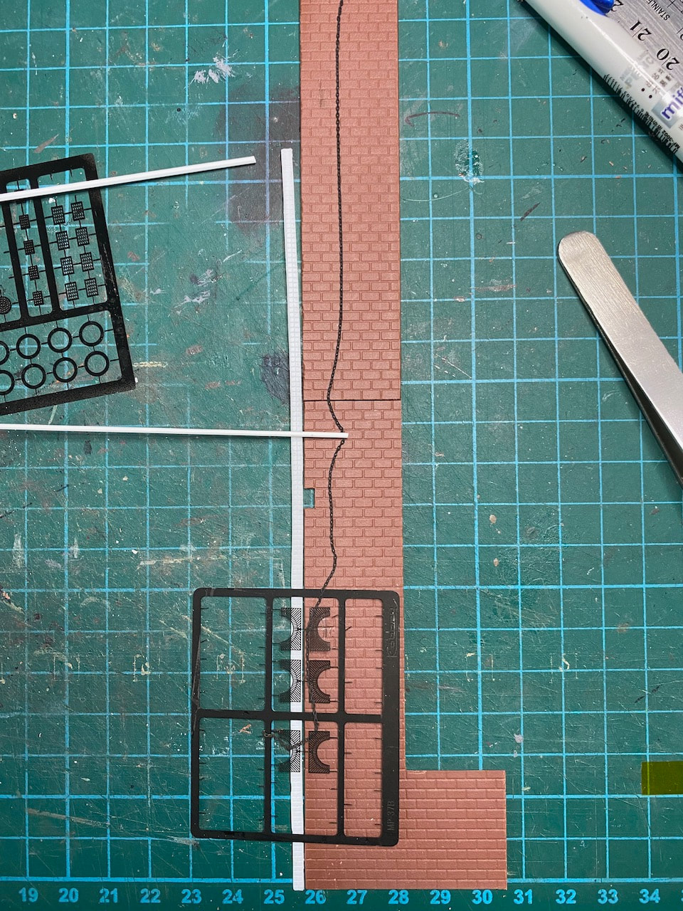 By the way, if you are looking for examples of different types of fences, there are 100 pages of photos in the landscape catalog here:
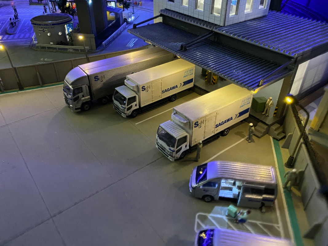
https://www.hokusei-kogyo.co.jp/catalog/ I have scratch built the sign board and other roof equipment using Evergreen styrene. The trucks and vans are from
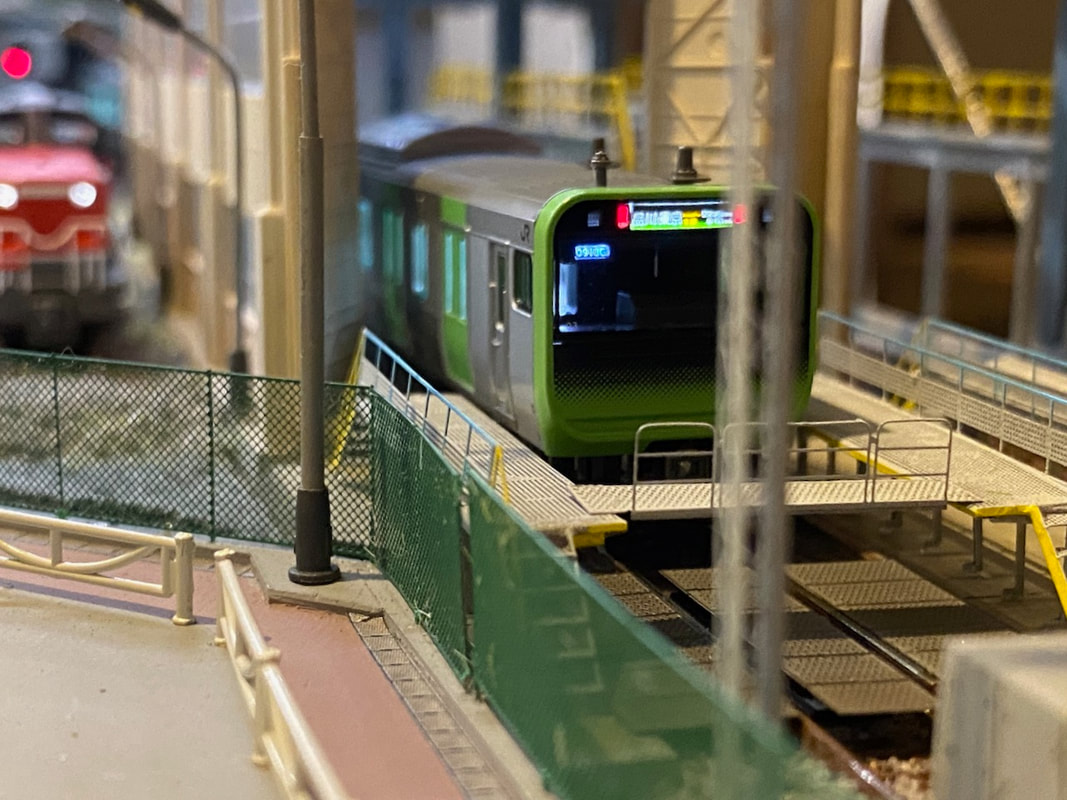
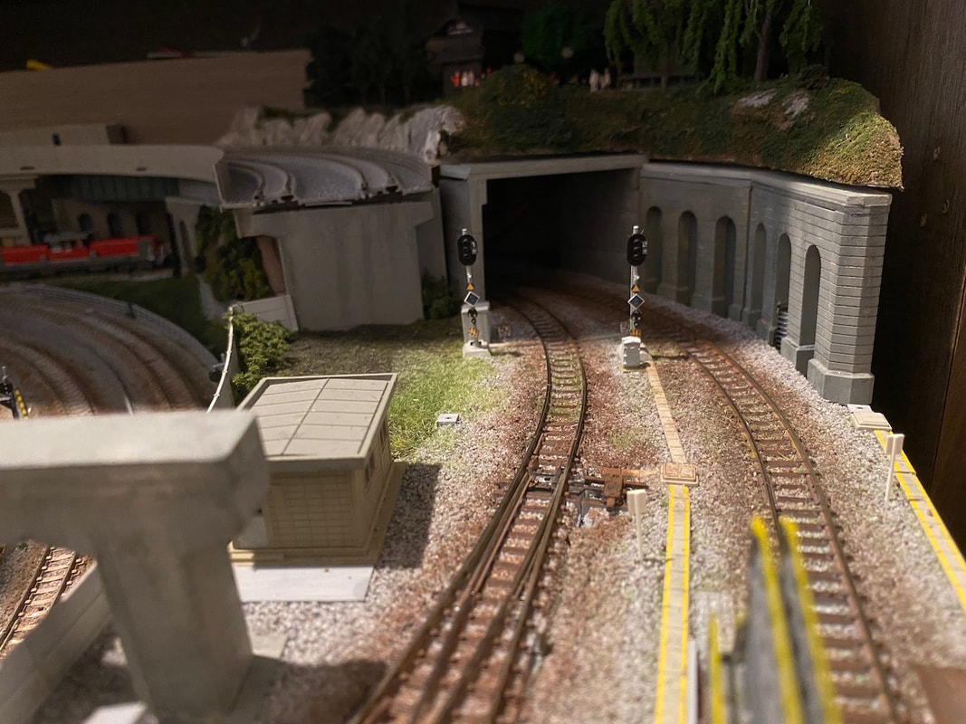
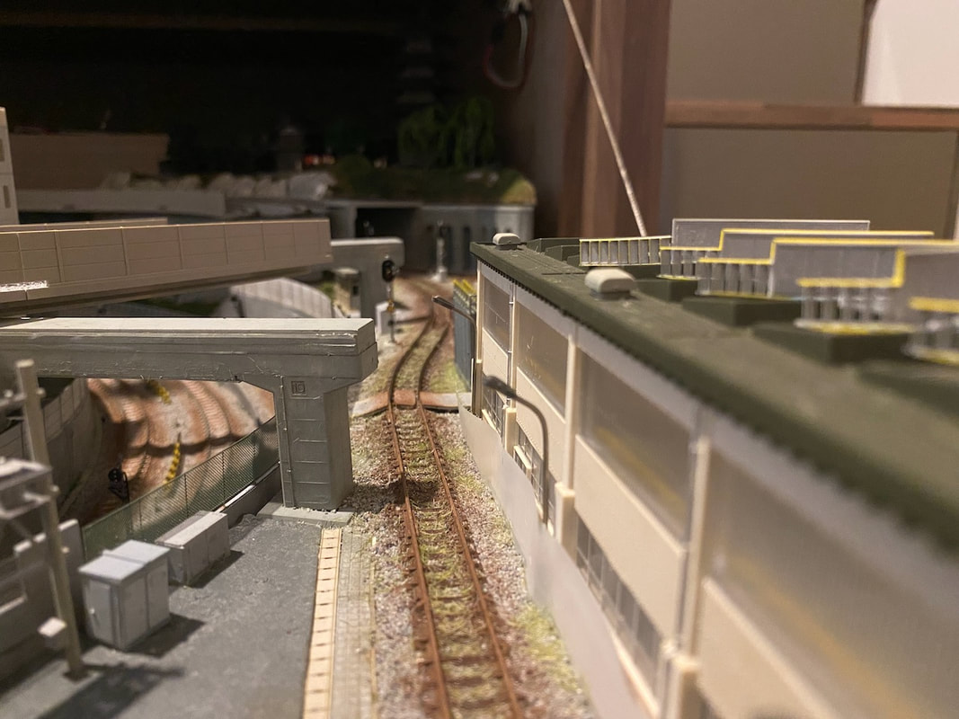
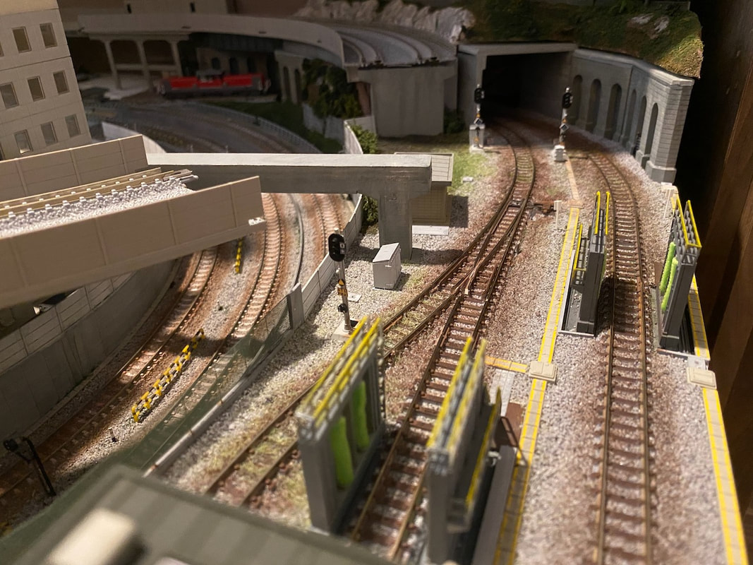
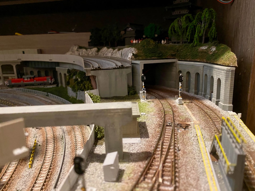
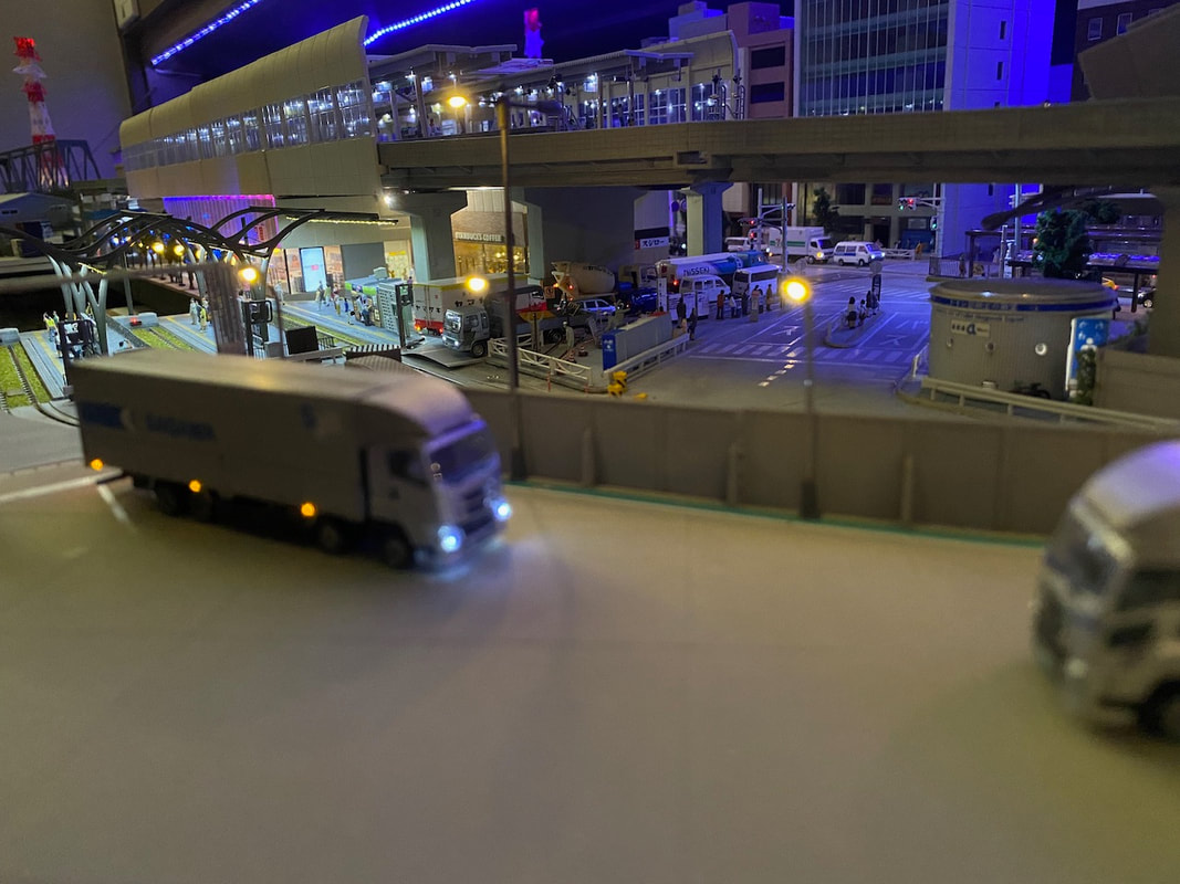
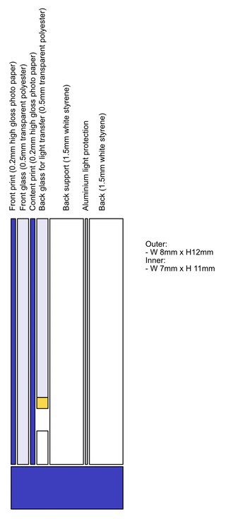
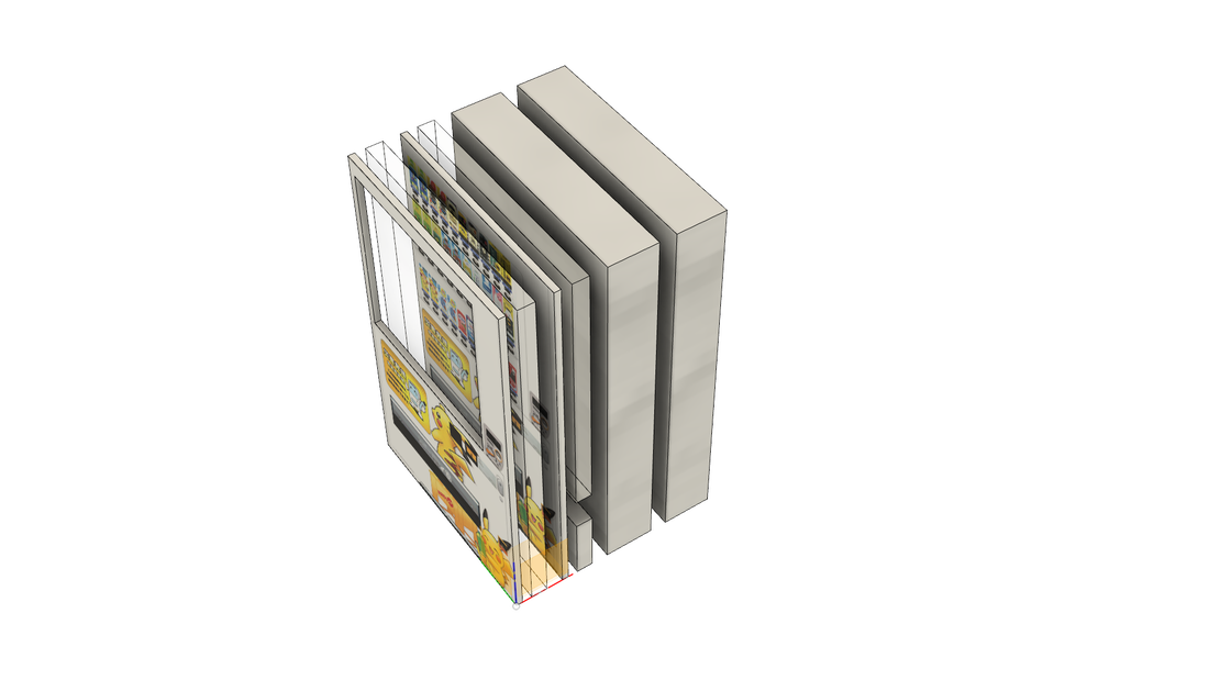
I decided to rebrand and expand the small truck terminal (Tomytec 069-2 Modern Truck Terminal). The expansion is done using Greenmax 2187 building kit, which is extremely flexible and easy to customise. This is the first stage of the construction. I have used DCC decoders from NGDCC, the DE29x6K and DF29x6K. The DE29x6K is for the motor car (Kumoha 813 207) and the DF29x6K is for the other end car (Kuha 813 207). I fitted each with two SMD LEDs for the headlights. Fitting the three cars with Kato 11-212 indoor lighting and Kato 29-353 FR11 DCC decoders has been easy, except in the motor car. Its floor is raised to make space for the motor and the car is not high enough to fit the FR11. I had to cut the floor on one side and solder the FR11 to the power strips and to the LED board. The concrete wall is made with Kobaru MB-07 Planoita · Concrete wall. The cable sleeve going to the signal is made with a metal spring (Wave A-Spring OP-016) The horizontal pipe is made with Evergreen styrene rod. This shows how I painted the Tomix tram tracks to give them better look. I decided to make a new set of vending machines for the east tram station (and other places in the city). They are build from multiple layers of styrene, transparent polyester and printed photo paper. 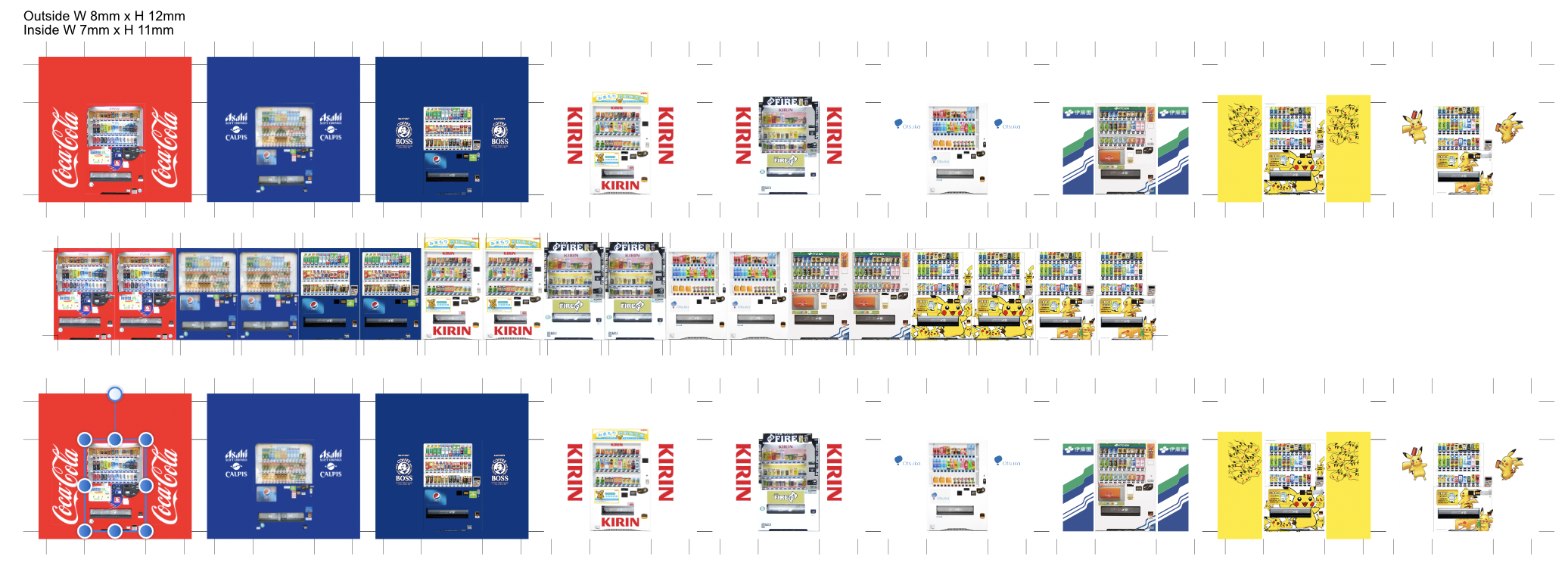
|
Categories
All
Latest videoArchives
November 2023
|


 RSS Feed
