|
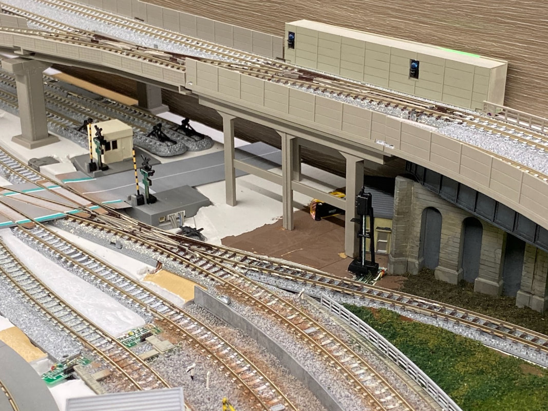
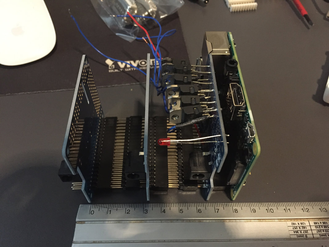
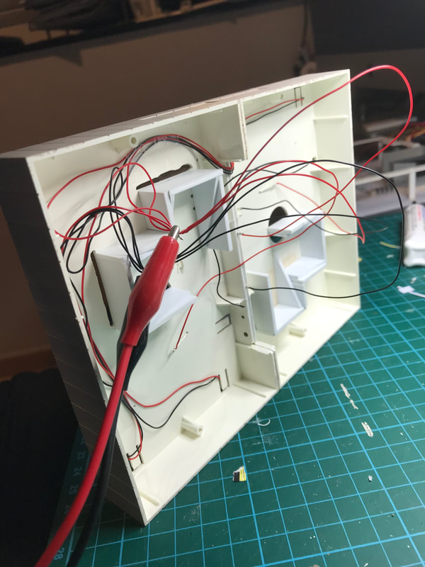
On the layout, I use an LED control system described here: https://shin-yukari.weebly.com/led-controller.html. It is based on Adafruit 12-Channel 16-bit PWM LED Driver modules spread all over the layout. They allow a central computer (a Raspberry Pi in my case) to control the hundreds of LEDs fitting the various buildings. In addition, I needed a similar control box on my workbench. This is a description of the system I have designed. 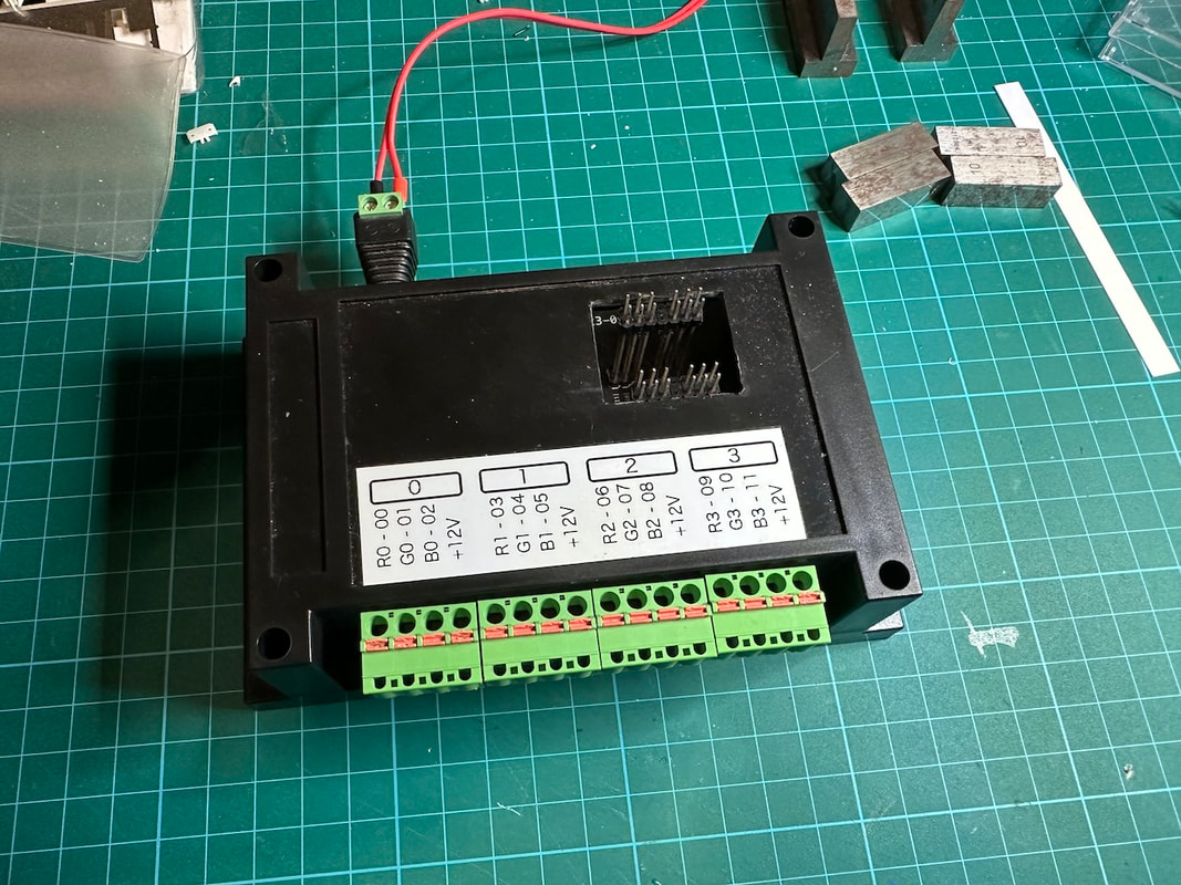 It uses the same Adafruit module and exposes the 12 LED outputs on terminal blocks with push-in connection, suitable for temporary connection (no soldering required, no screw). 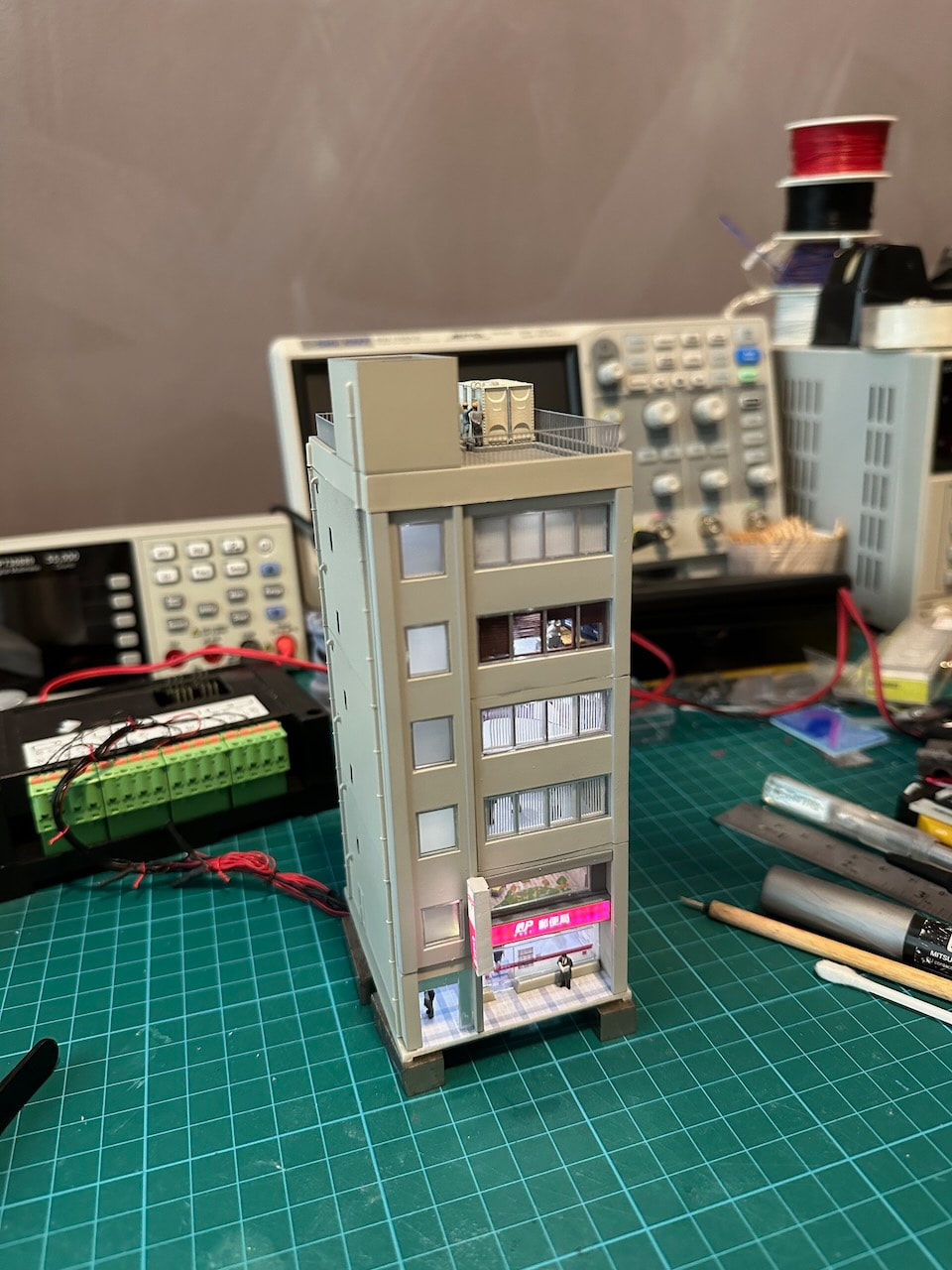 Here we see a building "under construction", with its wires attached to the control box. 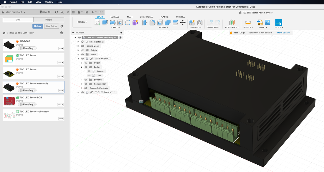 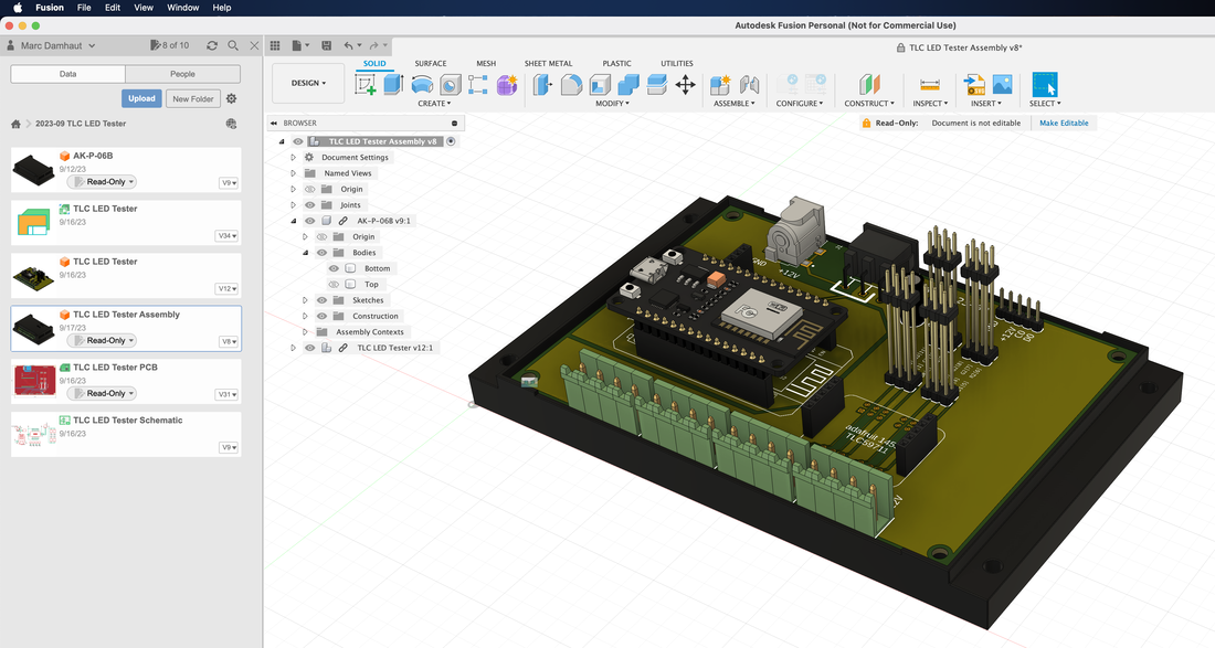 I have designed the PCB in Autodesk Fusion 360. The system is based on an ESP32 microcontroller connected to the Adafruit module and to the various connectors and terminal blocks. The ESP32 exposes a web page used to individually set the brightness of each LED. 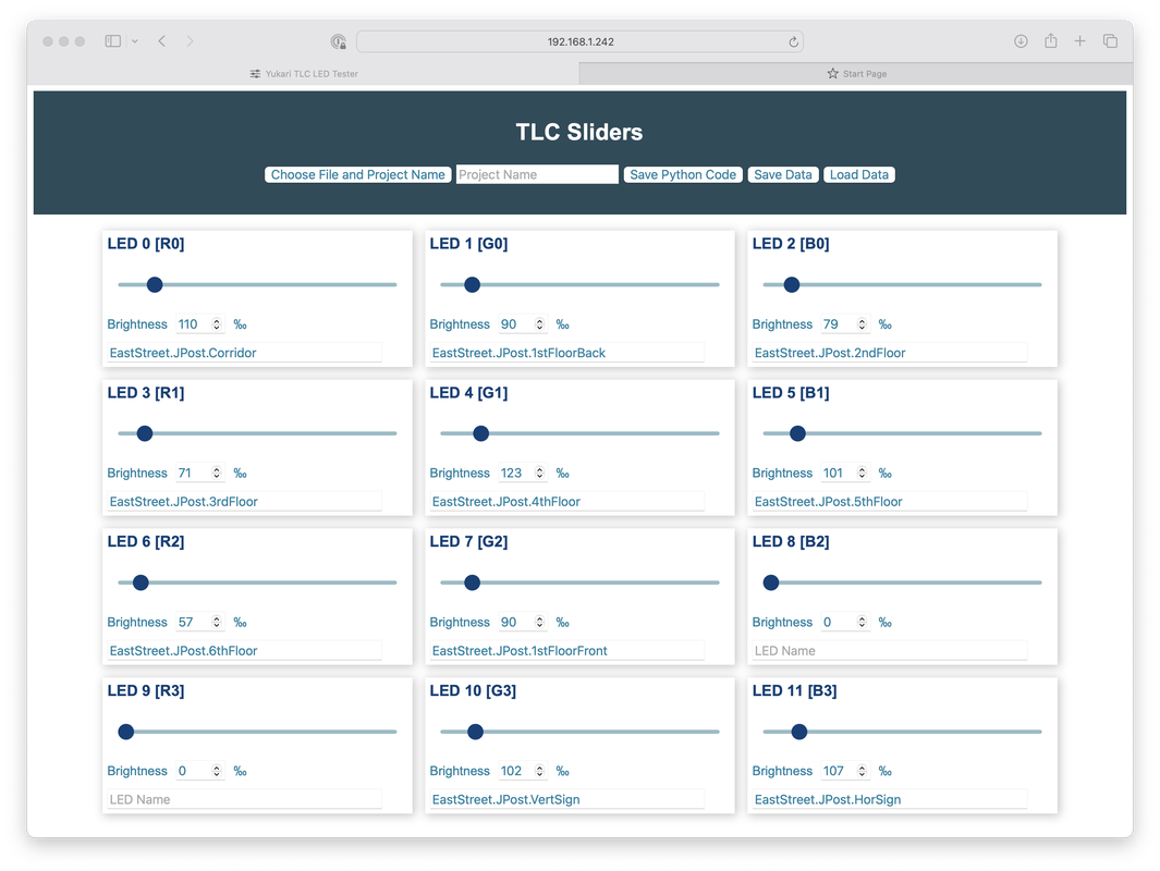
0 Comments
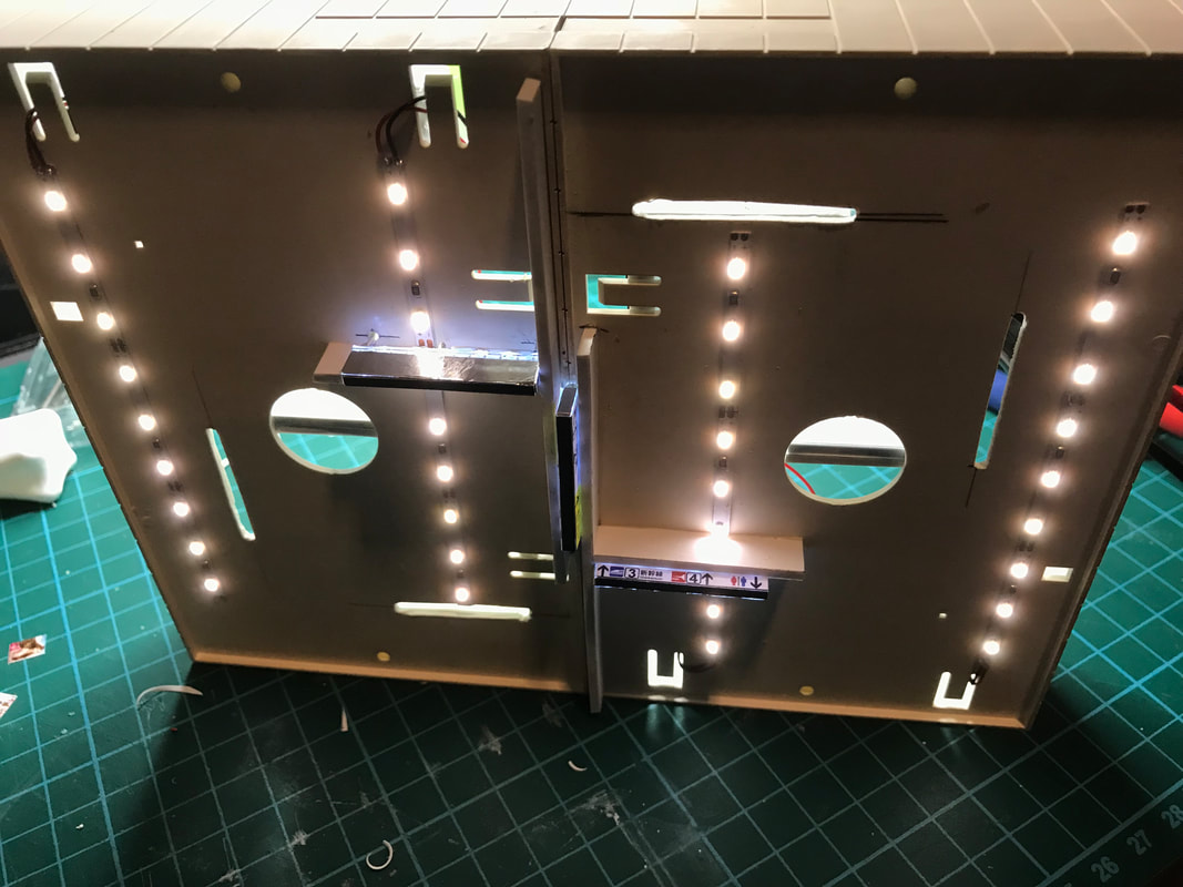
Each storey is lighted individually, using small light boxes. I needed to add more signals, so I made a new version of my Arduino Nano-based DCC signal controller. This one can control up to ten Tomix signals. Working on the construction site this week. First, new signboards and decals   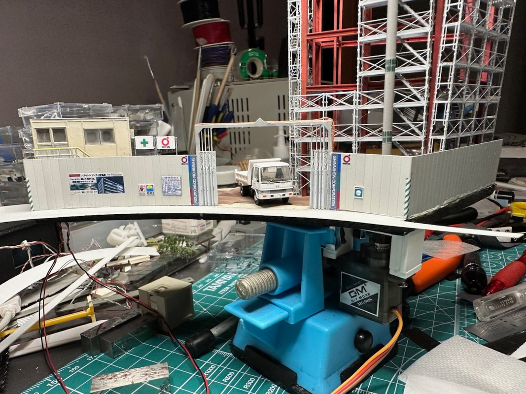 Then, the first tests of the moving crane. The servo motor (controlled by an Arduino Nano) is right below the board. The rotation is not super smooth, I'll have to work on that! Two years and five months ago, I managed to control a Tomytec bus by using an electromagnet under the road. I am now happy to report that I have finally been able to move the modules of the main street, bus interchange and Iwasehama station to the layout. All the wires for the bus control blocks, the hundreds of LED lights, the signals and the tracks are connected and everything seems to work fine. Well, not everything. There are still so many things to improve. These buses sometimes seem to have a mind of their own! Next (major) step: finish the tram layout, and make sure that trams and buses don't collide! For that, I'll have to teach the Raspberry Pi Python application controlling the buses to talk to Rocrail! Interesting challenge. - TFT display is 320x240 (240x320 portrait) ILI9341
- I use fbtft_device to drive the display - The video is a h.264 mp4 file played by mplayer Hardware components used:
* ESP32 (Lolin32) with 4BM Flash memory * Tourist Information: 0.96" 80x160 RGB IPS display with ST7735 driver (only the top 80x80 pixels are used and visible) Connections: DISPLAY ESP32 -------------------- GND GND VCC V3 SCL SCL (SPI Clock) SDA MOSI (SPI Data (to slave)) RES GPIO4 (Reset) DC GPIO2 (Data/Command) CS SS/5 (Chip Select) BLK GPIO15 Uploading files to the ESP32 flash: Install ESP32 Filesystem Uploader in Arduino IDE https://randomnerdtutorials.com/install-esp32-filesystem-uploader-arduino-ide/ https://github.com/me-no-dev/arduino-esp32fs-plugin/releases/ The size of the ESP32 SPIFFS partition can be set in the IDE as 1Mbyte or 3Mbytes. Place the video/image files inside the sketch folder, in a folder called "Data". Then upload all the files in the folder using the Arduino IDE "ESP32 Sketch Data Upload" option in the "Tools" menu. The sketch loads - an 80x80 pixel background image (back.jpeg) once at the beginning - a sequence of up to one thousand 40x80 images (videoNNN.jpeg) stored in the built-in flash memory. The videoNNN.jpeg files are built as follows: - Scale and crop the source video to 40x80 (portrait) with Handbrake - Extract the .jpeg files with ffmpeg: ./ffmpeg -i video.mp4 -s 40x80 -r 10 video%03d.jpeg Trying to fit 0402 LEDs into Kato 23-214 traffic lights. It works, but I am just going to install one LED (either green or red) in each signal. 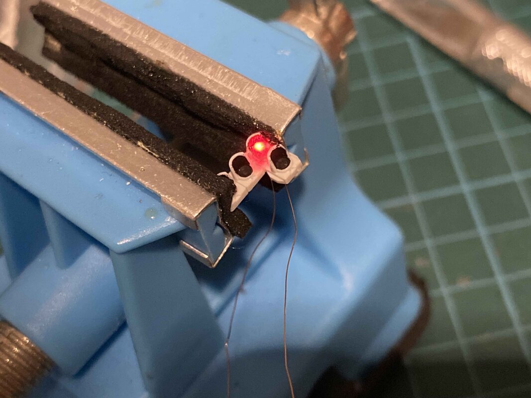 This is where the bus guide wire crosses the tram track: 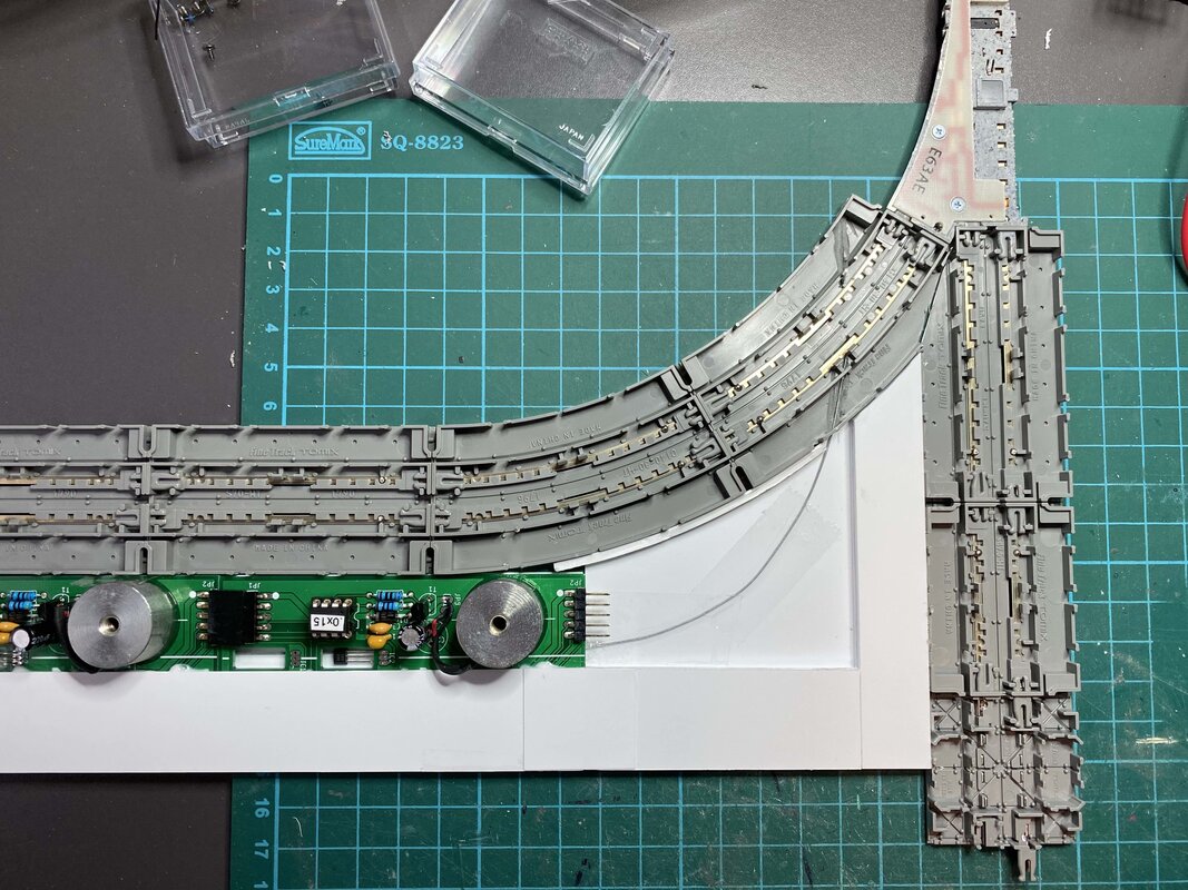 Next step: the bus interchange. I have built a switch for the bus: a servo motor moves the guide wire towards one of the two positions. It works 🙂 Today, I have started the integration of the system into the python application that runs on the raspberry pi (the same one that controls all the LEDs on the layout). I have added a screen to control the busses, it looks like that: 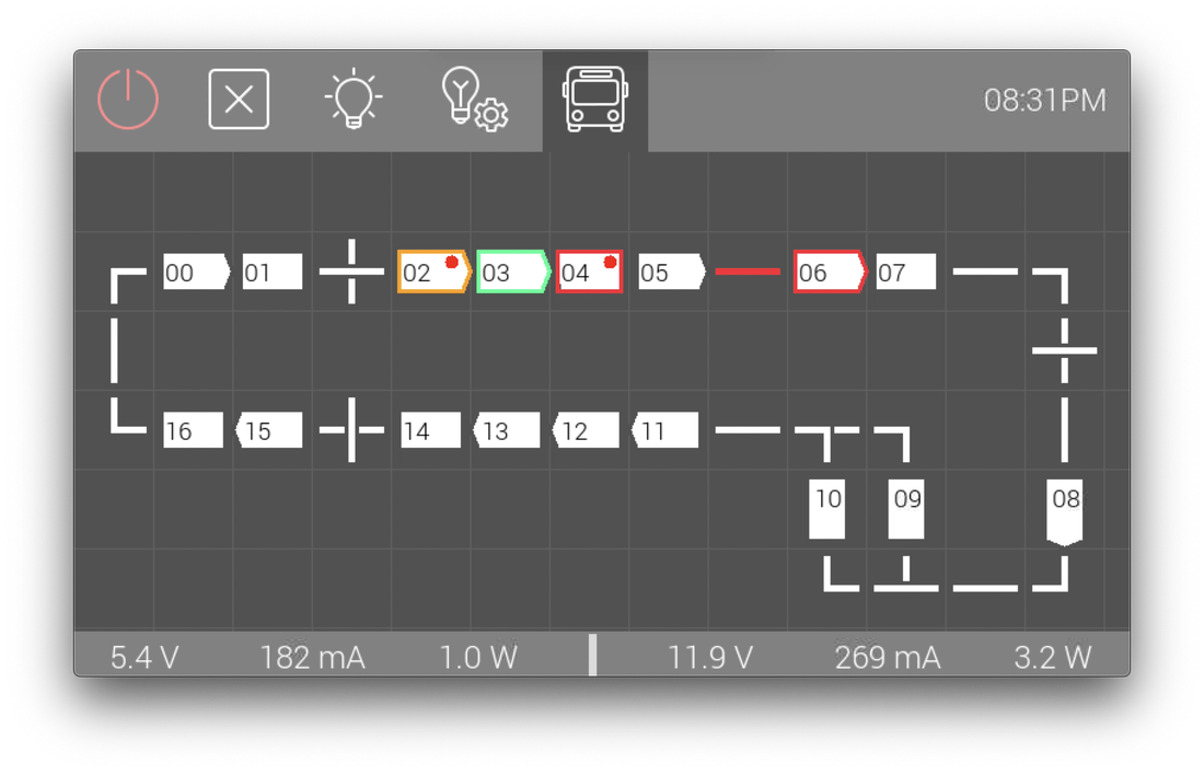 Each bus block is a white rectangle. The block is highlighted
The application makes sure that there is no collision. The video below shows the results of very the first test: For more than a year now I am trying to control the Tomytec busses (fitted with a BM-01, BM-02 or BM-03 motor). My ultimate goal is to make the street at the centre of my layout look like this: There will be
 They will all be connected to a Raspberry Pi, which will be able to control the traffic flow. All of this is still under development, but this weekend I have been able to connect eight bus blocks, and this is the result (that I find really encouraging):
 I changed the "sky" lighting to two rows of individually-controllable RGB+Natural White LEDs.
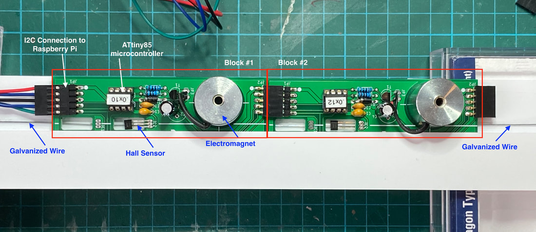
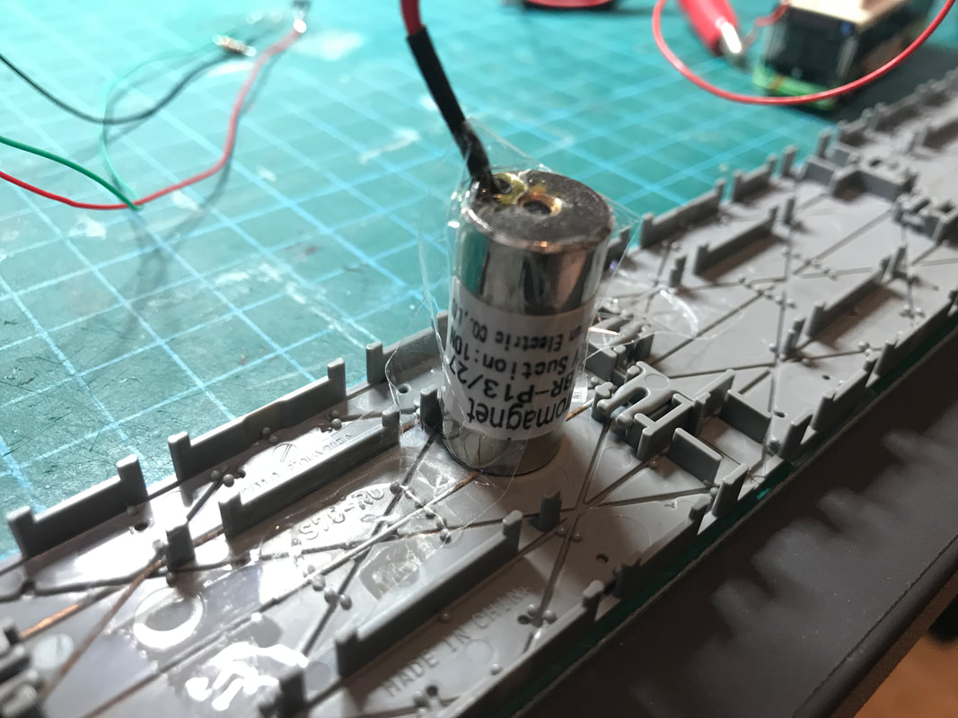
In this first test, I used a 13x27 12V 1W 10N (size 13x27mm, 12 volts, 1 watt, 10 newton force) electromagnet that can easily be purchased from AliExpress (look for solenoid, electromagnet, or follow this link). Its power consumption is about 100mA, which is reasonable, and the heat dissipation is not too high. The bus stops when the electromagnet is powered, then restarts when I switch off the power supply.
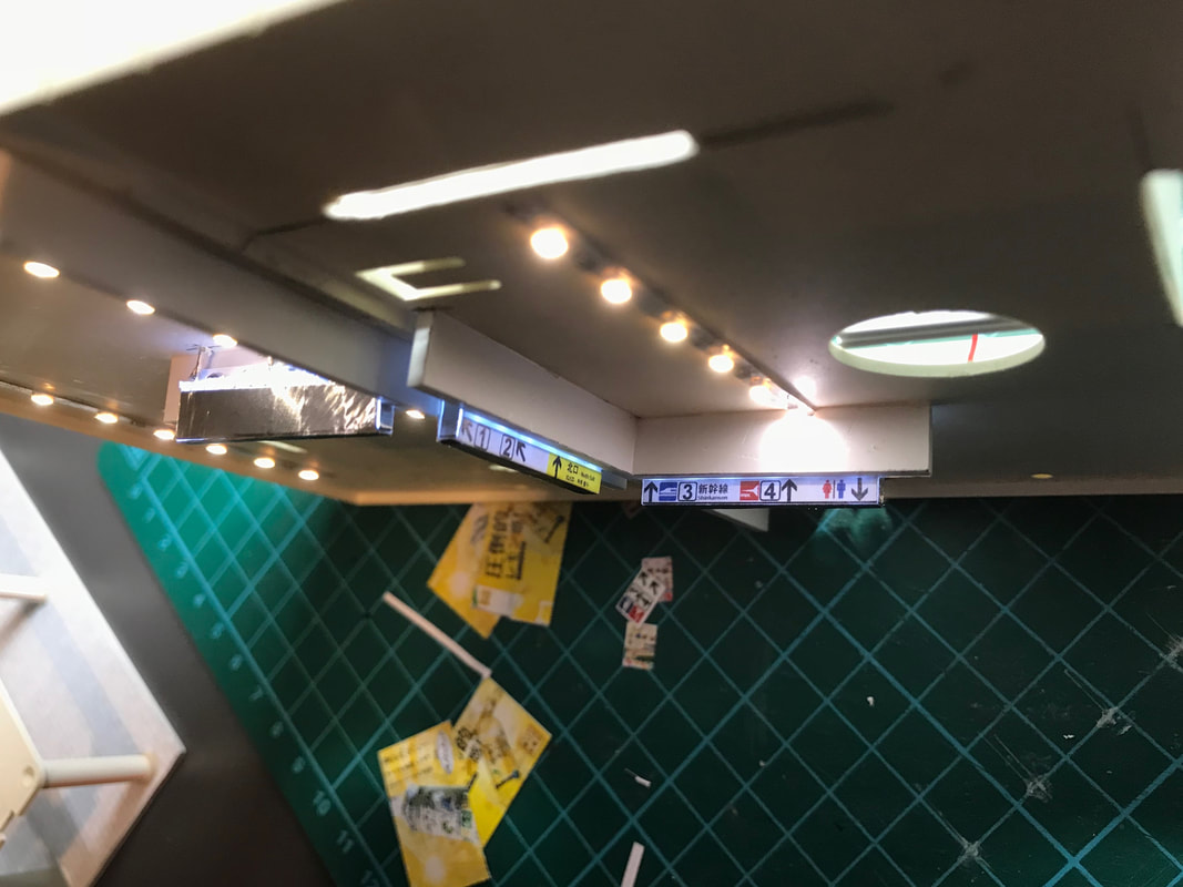
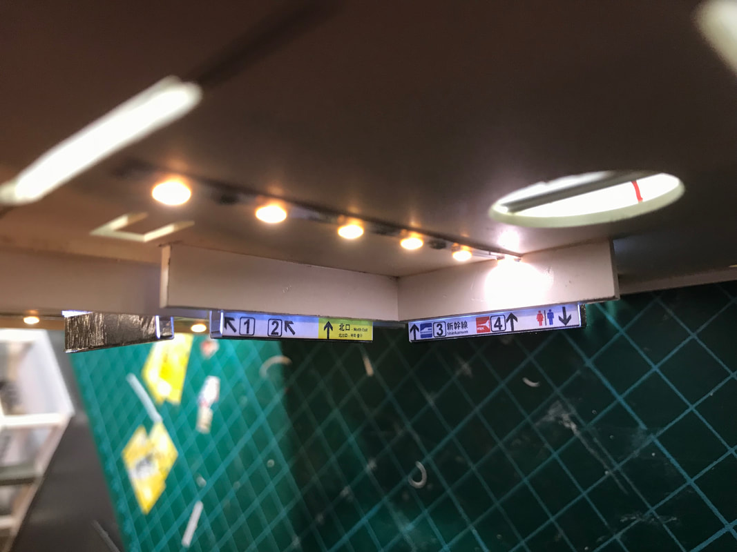
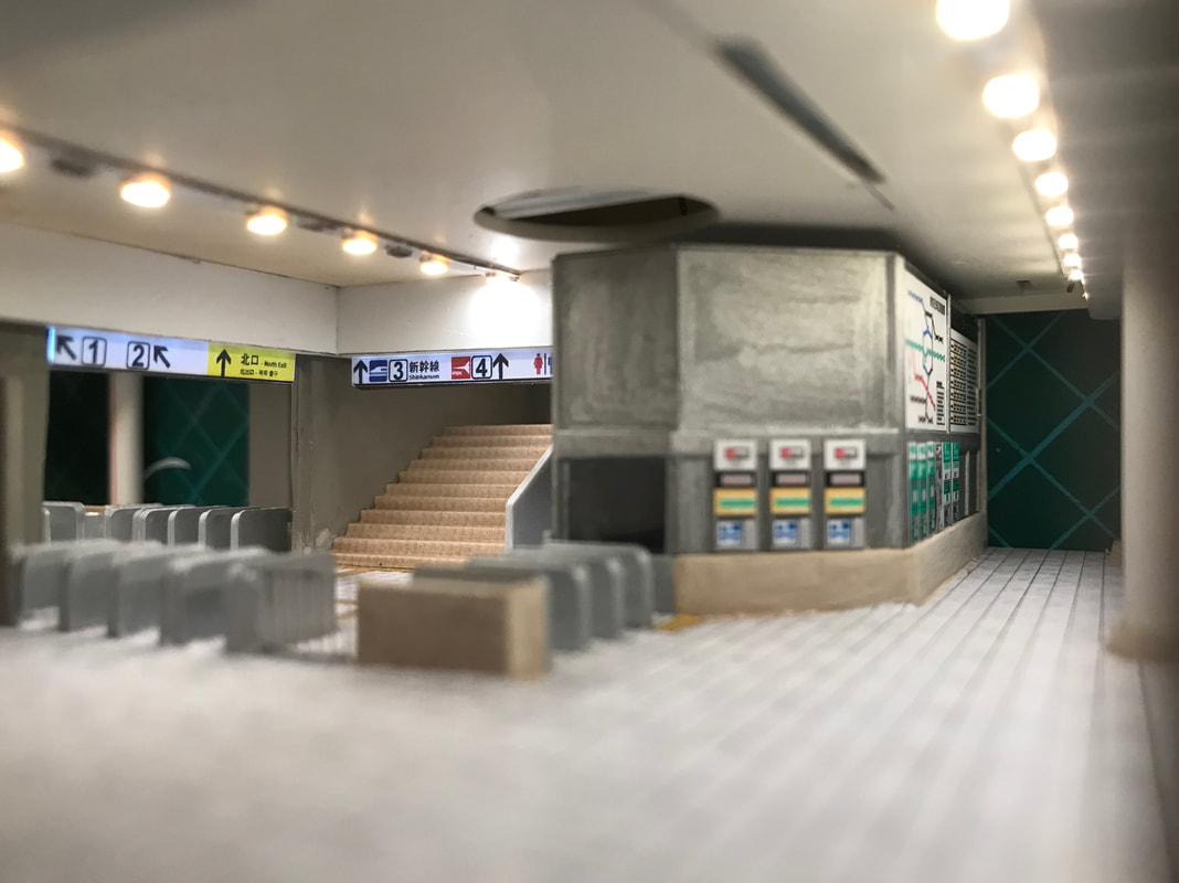
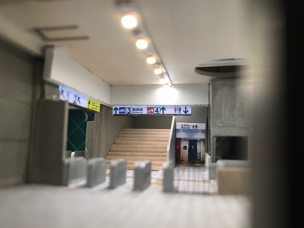
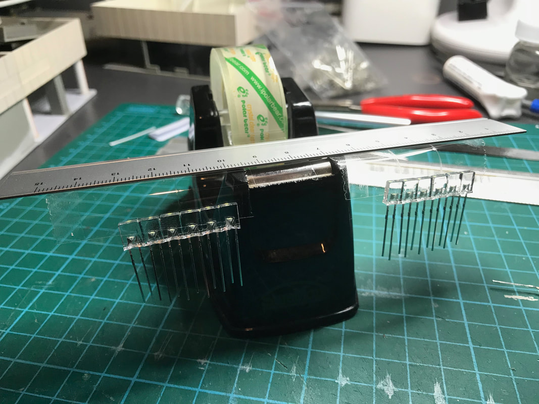
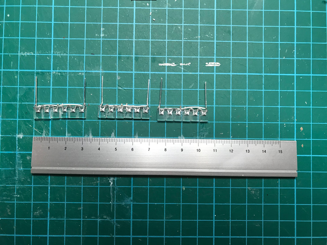
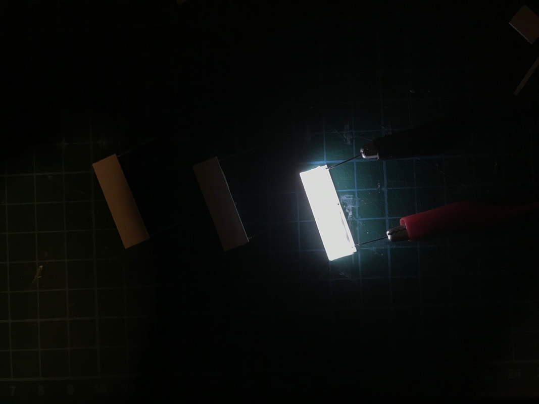
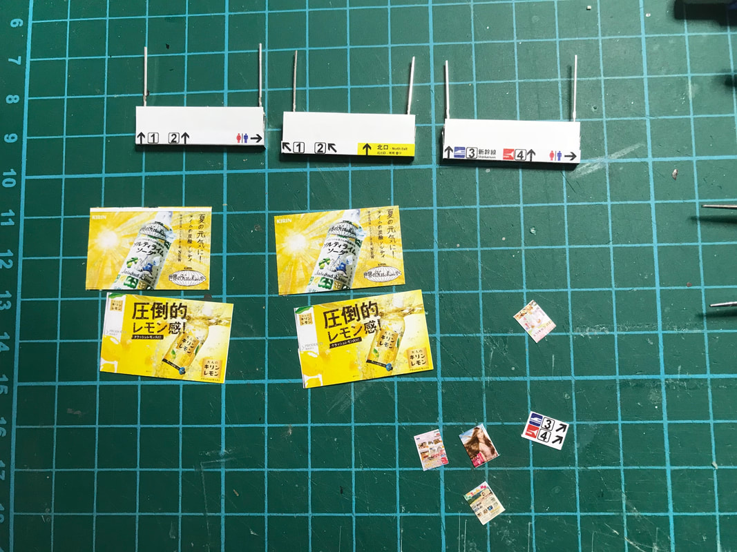
Today I tested the signs and ceiling lights of the Shin-Yukari station entrance hall. To make lighted sign boards, I glued together six square white LEDs (connected as two groups of three), then added a thin styrene sheet before pasting the signs.
Code Editor
 This is the very first version of my lighting controller. It is based on a Raspberry Pi and several Adafruit 16-Channel PWM / Servo HAT modules. I will eventually not use these modules (see future posts about my lighting controller). 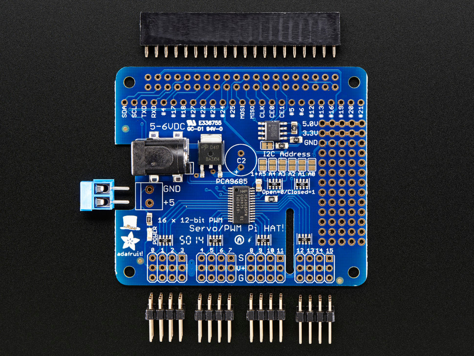 |
Categories
All
Latest videoArchives
November 2023
|

 RSS Feed
